Multi-port diverter valve assembly with integral detent

a diverter valve and integrated technology, applied in the direction of valve details, valve arrangement, thin material handling, etc., can solve the problems of increasing the cost of such valve installation, increasing the complexity of installation, and reducing the service life of the diverter valve, so as to reduce the cost of installation and maintenance costs. , the added expense is a barrier to installing multiple showerheads in those applications, and the diverter valve assembly is a bit expensiv

Active Publication Date: 2006-06-27
DELTA FAUCET COMPANY
View PDF34 Cites 19 Cited by
  • Summary
  • Abstract
  • Description
  • Claims
  • Application Information

AI Technical Summary

Benefits of technology

[0008]A flow diverter valve assembly according to one embodiment of the present invention comprises a base housing defining a plurality of flow passageways, a rotatable diverter cartridge positioned within the base housing and defining a plurality of detent recesses. A cap is assembled to the base housing and is positioned between the base housing and the rotatable diverter cartridge. The cap includes at least one deflectable detent finger that is constructed and arranged to sequentially engage each of the plurality of detent recesses. By means of a handle for manually rotating the diverter cartridge relative to the cap, the disclosed structure enables the user to change from one finger-to-recess detent engagement to another finger-to-recess detent engagement. Each detent engagement position corresponds to a different selection of hydraulic devices to be supplied fluid by means of the diverter valve assembly.

Problems solved by technology

Installation of such valves increases cost, complexity, and installation time.
The added expense is a barrier to installing multiple showerheads in those applications where cost is of concern.
While this type of ball detent structure provides the tactile feel and may provide an audible “click”, it does represent a somewhat expensive addition to the diverter valve assembly.

Method used


Image

  • Multi-port diverter valve assembly with integral detent
  • Multi-port diverter valve assembly with integral detent
  • Multi-port diverter valve assembly with integral detent

Examples


Embodiment Construction

[0024]For the purposes of promoting an understanding of the principles of the invention, reference will now be made to the embodiments illustrated in the drawings and specific language will be used to describe the same. It will nevertheless be understood that no limitation of the scope of the invention is thereby intended, such alterations and further modifications in the illustrated device, and such further applications of the principles of the invention as illustrated therein being contemplated as would normally occur to one skilled in the art to which the invention relates.

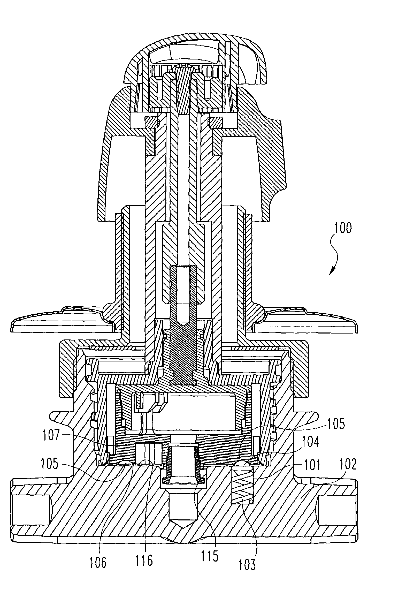
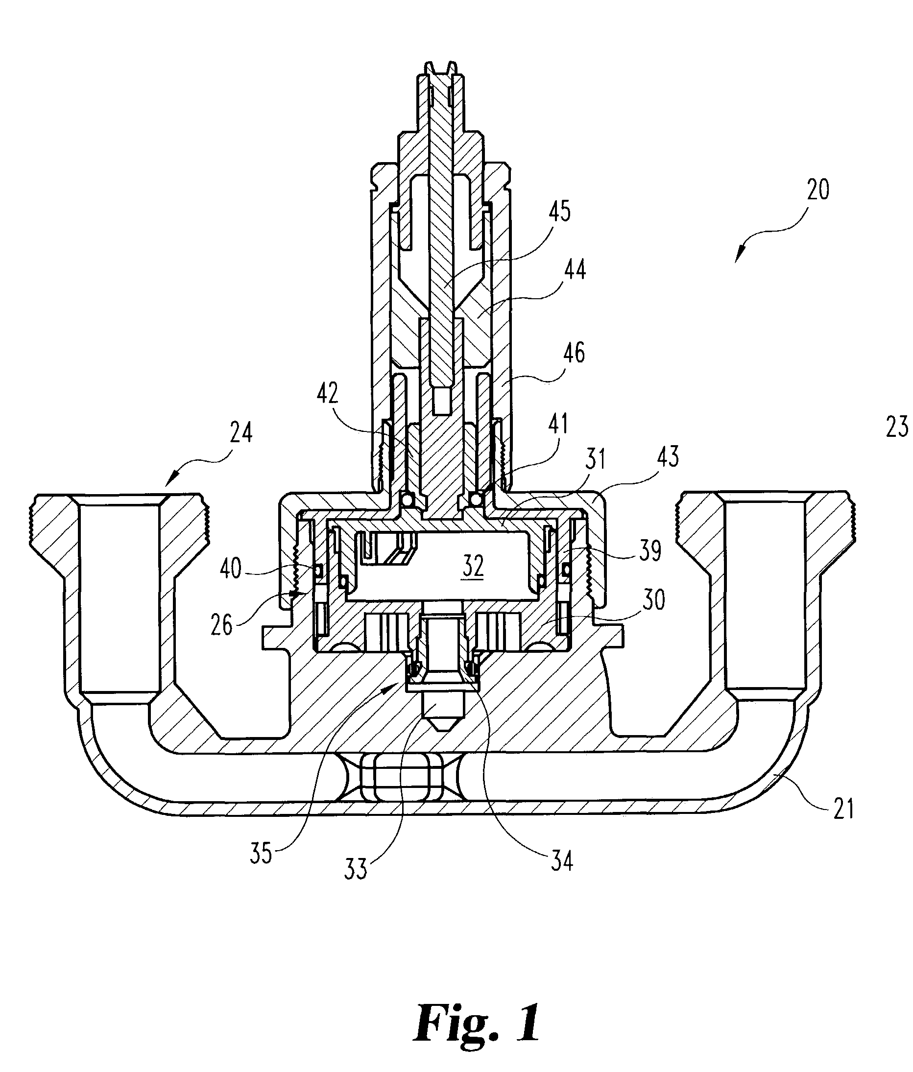
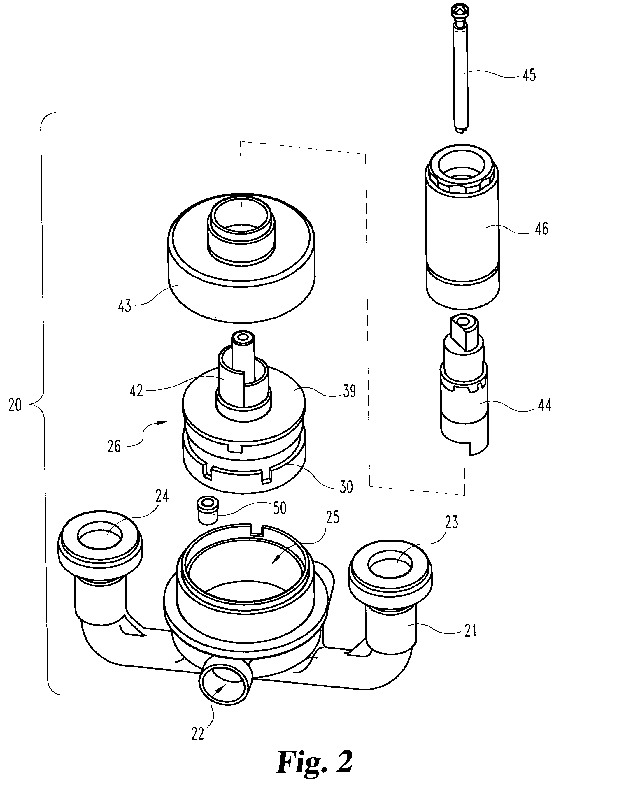
[0025]Referring to FIGS. 1 and 2, a first style of a multi-port diverter valve assembly 20 is illustrated. Assembly 20 has been illustrated, and is described herein, in order to explain generally the structure and functioning of this type of multi-port diverter valve assembly so that the improvements provided by the present invention will be easier to explain and understand.

[0026]Diverter valve assembly 20 incl...


PUM


Abstract

A multi-port diverter valve assembly with an integral detent feature includes a valve body and a diverter valve cartridge and cap combination wherein the cap includes one or more deflectable fingers positioned so as to “detent” into one or more detent recesses formed in a lower cartridge portion of the rotatable cartridge. In order to provide fluid communication to external hydraulic devices with a total of six selection options, a total of six detent recesses are provided. In the preferred embodiment, there are two deflectable fingers approximately 180 degrees apart. An O-ring is positioned between the deflectable fingers and the valve body in order to provide part of the resistance force against the deflectable fingers so as to provide a tactile feel to the user when a selected detent position is reached by rotation of the diverter valve cartridge within the valve body.

Description

BACKGROUND OF THE INVENTION[0001]The present invention relates in general to multi-port diverter valves for directing a liquid, typically water, from a mixing valve to one or more of a plurality of selectable outlets. The outlets are associated with various hydraulic devices, such as a hand wand, a showerhead, and a body sprayer. More specifically, the present invention relates to the modification of such a multi-port diverter valve to include an integral detent structure and the elimination of a more costly spring-loaded stainless steel ball that is used to provide a detent feature.[0002]A diverter valve is typically designed to be assembled between a flow control device or a valve such as a mixing faucet and one or more other hydraulic devices. One common example of a diverter valve is the use of a mixing valve for a shower and tub combination. The mixing valve provides proportional quantities of hot and cold liquids, typically water. The typical style of diverter valve is actuate...

Claims


Application Information

Patent Timeline
Patent Type & Authority Patents(United States)
IPC IPC(8): F16K11/072F16K35/02
CPCF16K35/027F16K11/072Y10T137/86501Y10T137/86863
Inventor MARTY, GARRY R.
Owner DELTA FAUCET COMPANY
Why Eureka
Try Eureka