
Compression pipe repairing and reinforcing methods

a compression pipe and pipe joint technology, applied in fluid pressure sealing joints, sleeve/socket joints, mechanical equipment, etc., can solve the problems of internal tight fitting sleeves loosening and separation of pipes, affecting the integrity of operating oil and gas pipelines, and affecting the flow of products

Active Publication Date: 2006-06-27
BJ SERVICES CO
View PDF19 Cites 20 Cited by
  • Summary
  • Abstract
  • Description
  • Claims
  • Application Information

AI Technical Summary

Benefits of technology

"The patent describes methods for repairing and rehabilitating pipes with defects. The methods involve applying split sleeves to the pipe and using a compression unit to create a uniform compressive hoop strain throughout the pipe. This strain can exceed a certain level of microstrain. The methods can also involve using connector plates to connect the split sleeves and monitoring the distance between measurement marks to measure the compressive force. The technical effects of the methods include improved pipe strength and durability, as well as reduced likelihood of future leaks or failures."

Problems solved by technology

The integrity of operating oil and gas pipelines can be adversely affected by damage caused by mechanical damage, corrosion, stress corrosion cracking, hydrogen induced cracking, or by other causes.
This requires the entire pipeline to be shut down, which may prove economically disadvantageous.
This is both costly and disruptive to the flow of product through the pipeline.
Moreover, if installed at prevailing operating pressure, the external tight-fitting sleeves can become loose and separate from the pipe if the operating pressure later drops for any reason.
While this method addresses the limitation of the prior sleeve repair methods and substantially reduces the risk of possible sleeve separation from the pipe after a pressure drop, some weaknesses remain that may limit its use under certain conditions.
This uncertainty may not be acceptable in those cases where the operator of the pipeline requires assurance that a specific level of a compressive strain is maintained in the pipe wall under all expected operating conditions.
If this type of repair sleeve is installed at lower operating pressure than the one to be used in the future, an additional uncertainty may be introduced regarding the sleeve's ability to effectively contain such cracks after the operating pressure has been restored to the higher expected level.
This increased uncertainty may not be acceptable to the operator who may need to select a repair alternative that provides more reliable control of this type of hazard.
Additionally, the need to uniformly heat the sleeve to fairly high temperature and maintain this temperature while the sleeve halves are being welded together is difficult to meet consistently under normal field conditions.
This difficulty stems from the fact that the sleeve is in a very close contact with the operating pipeline that typically acts as a significant heat sink that causes the applied heat to dissipate rapidly.
Moreover, manipulating several heat sources while the welding of the sleeve is in progress increases the level of safety hazard that is associated with this type of repair.
However, as shown by the experimental data contained therein, the resulting repair of the pipe section fails to place the pipe section in compression, as the pipe section remains in tension after repair.
Further, as evidenced by the experimental data contained therein, the resulting repair fails to provide uniform strain along the entire length of the pipe section.
The repair methods currently used in the industry are disruptive to pipeline operations, involve considerable dependence on the individual operators, and may present safety risks when heat sources are used near oil and gas supplies.
Further, none of the prior art methods results in a repair that uniformly applies compressive hoop strain to the inner diameter of the pipe section along its entire length; nor do the prior art methods maintain this compressive strain under all operating conditions the pipeline may experience after the repair.

Method used


Image

  • Compression pipe repairing and reinforcing methods
  • Compression pipe repairing and reinforcing methods
  • Compression pipe repairing and reinforcing methods

Examples


examples

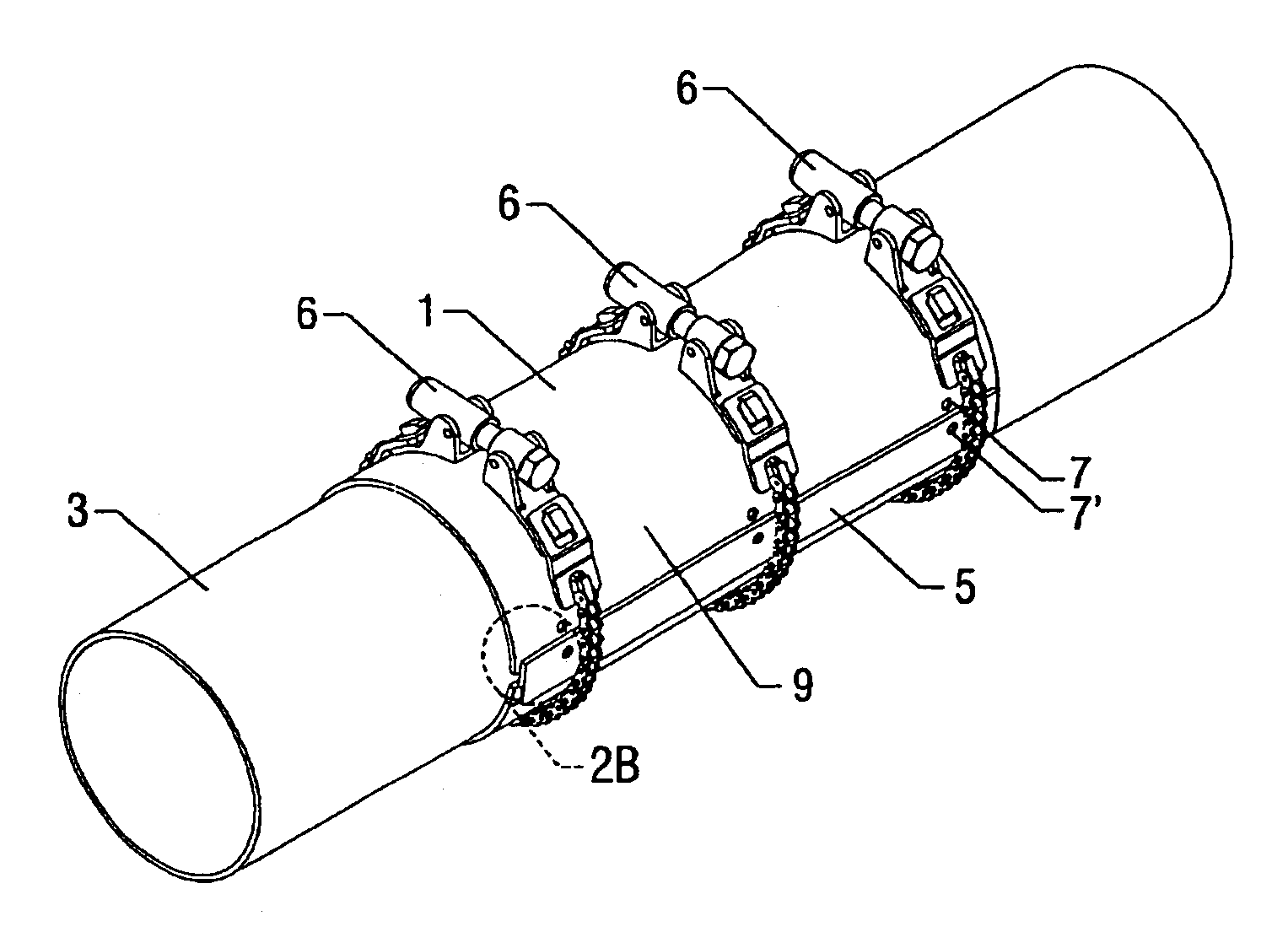
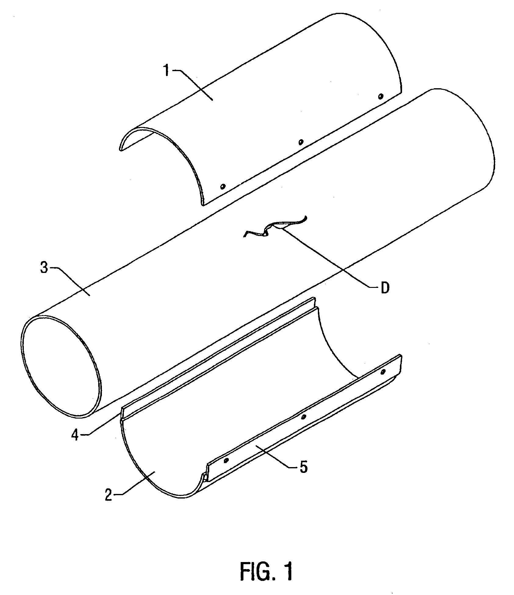
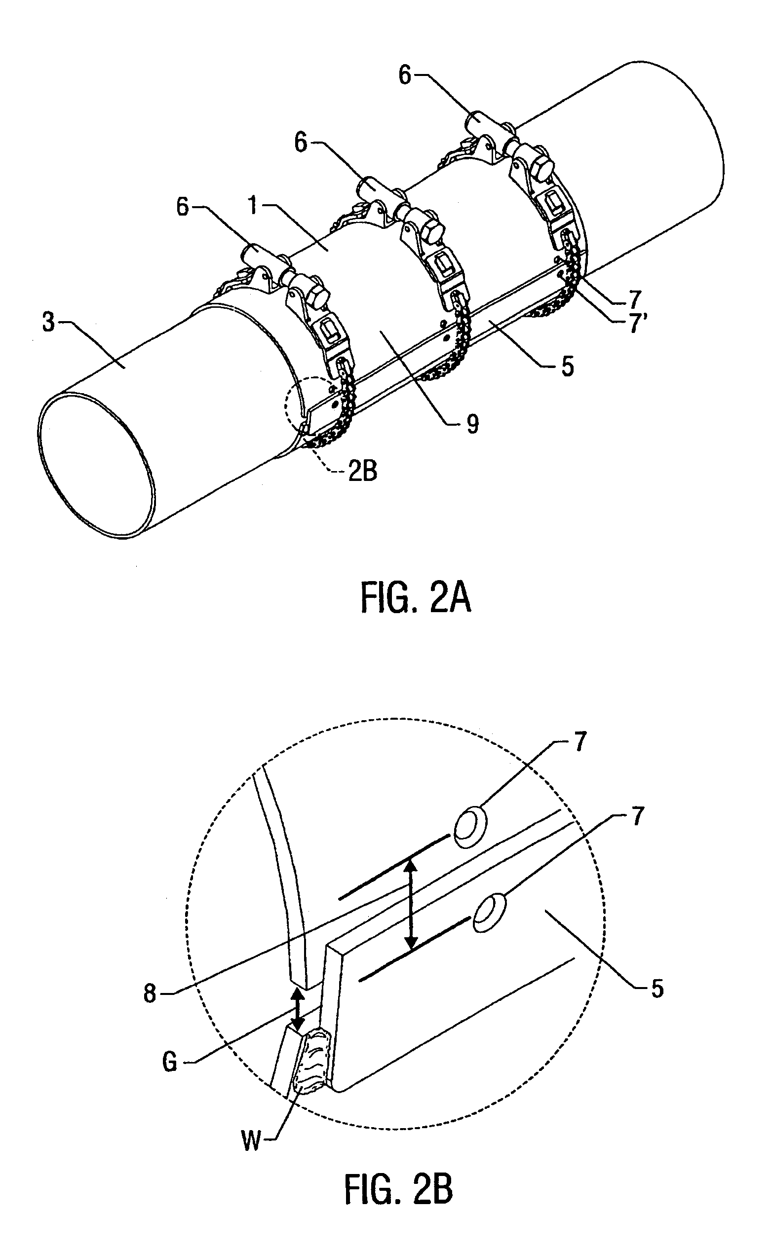
[0069]To verify the efficacy of one embodiment of the above-described methods, an experiment was performed utilizing the apparatus and method described above with respect to FIGS. 4A–7E. Prior to performing the method, strain gages were applied to the inner diameter of the section of pipe to be repaired or reinforced along the entire length of the pipe section.

[0070]Compressive force was then calculated and applied as described above and measurements from the various strain gages were recorded over time. As can be seen from the following three tables, as the compressive force was calculated and applied, the section pipe, originally experiencing tensile hoop strain (shown here as positive values) at the installation pressure of 435 p.s.i., subsequently experienced compressive hoop strain excess over 100 microstrain in compression (shown here as negative values) after the repaired section was pressurized to the specified maximum operating pressure of 740 p.s.i. In this way, the method...


PUM

PropertyMeasurementUnit
lengthaaaaaaaaaa
distanceaaaaaaaaaa
distanceaaaaaaaaaa

Abstract

A method of repairing a section of pipe is described. The method includes applying a first split sleeve and a second split sleeve to the pipe section, functionally associating the first end of the first split sleeve with the first end of the second split sleeve, and applying a compressive force until the internal diameter of the pipe experiences compressive shear hoop strain. The method described produces substantially uniform compressive hoop strain along the length of the pipe section, and may exceed a predetermined value, such as 100 microstrain in compression, for example. The amount of force required may be calculated utilizing maximum operating conditions. The method described may produce an acceptable permanent repair by ensuring that the inner diameter of the section of pipe experiences compressive strain. Also described is a method of reinforcing a section of pipe utilizing these apparatus and methods.

Description

CROSS REFERENCE TO RELATED APPLICATIONS[0001]The present application claims priority to U.S. Provisional Patent Application Ser. No. 60 / 395,966 filed Jul. 15, 2002, the contents of which are incorporated herein by reference.FIELD OF THE INVENTION[0002]The present invention relates to a permanent reinforcing repair of gas and oil pipelines damaged by injurious defects. More specifically, methods are disclosed that apply a predetermined external mechanical force through a metal sleeve to permanently compress a pipe beneath such that the pipe experiences a substantially uniform, compressive hoop strain (i.e. strain measured on the inner diameter of the pipe) along its length to achieve an acceptable permanent repair of crack-like defects subjected to fluctuating loads. The method may include calculating the compressive force for the pipe under maximum operating conditions.DESCRIPTION OF RELATED ART[0003]The integrity of operating oil and gas pipelines can be adversely affected by damag...

Claims


Application Information

Patent Timeline
Patent Type & Authority Patents(United States)
IPC IPC(8): F16L55/16B21D1/00B21D3/00F16L55/17F16L55/172
CPCF16L55/172
Inventor KAKOSCHKE, DALEPAVON, RUBENUREDNICEK, MIREK
Owner BJ SERVICES CO
Learn More