Partition structures for the interior of an ink container

a technology for partitioning structures and ink containers, which is applied in printing and other directions, can solve the problems of mixing ink in one chamber, and achieve the effects of optimizing the isolation of the chambers from one, minimizing color mixing, and improving versatility

Inactive Publication Date: 2006-06-27
HITACHI CONSUMER ELECTRONICS CORP +1
View PDF7 Cites 14 Cited by
  • Summary
  • Abstract
  • Description
  • Claims
  • Application Information

AI Technical Summary

Benefits of technology

[0005]It is accordingly an outstanding object of the present invention to provide improved partition designs for the interior of an ink container shell of an ink container for an ink jet cartridge.
[0006]Another object is the provision of an ink container shell of the foregoing character having improved versatility with respect to selectively designing the volumes of the ink chambers.
[0007]Yet another object is the provision of a container shell of the foregoing character which advantageously optimizes isolation of the chambers from one another to minimize color mixing in the event of leakage between chambers.

Problems solved by technology

Accordingly, a leakage problem across a partition wall between adjacent chambers can only result in the mixing of the ink in the one chamber with that in the adjacent chamber.

Method used


Image

  • Partition structures for the interior of an ink container
  • Partition structures for the interior of an ink container
  • Partition structures for the interior of an ink container

Examples


Embodiment Construction

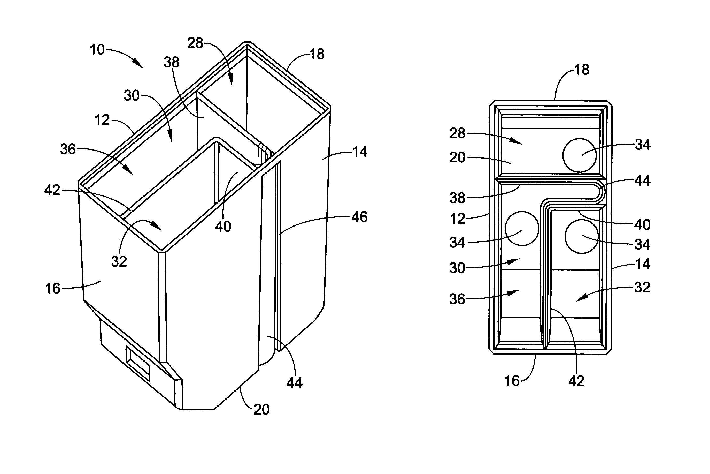
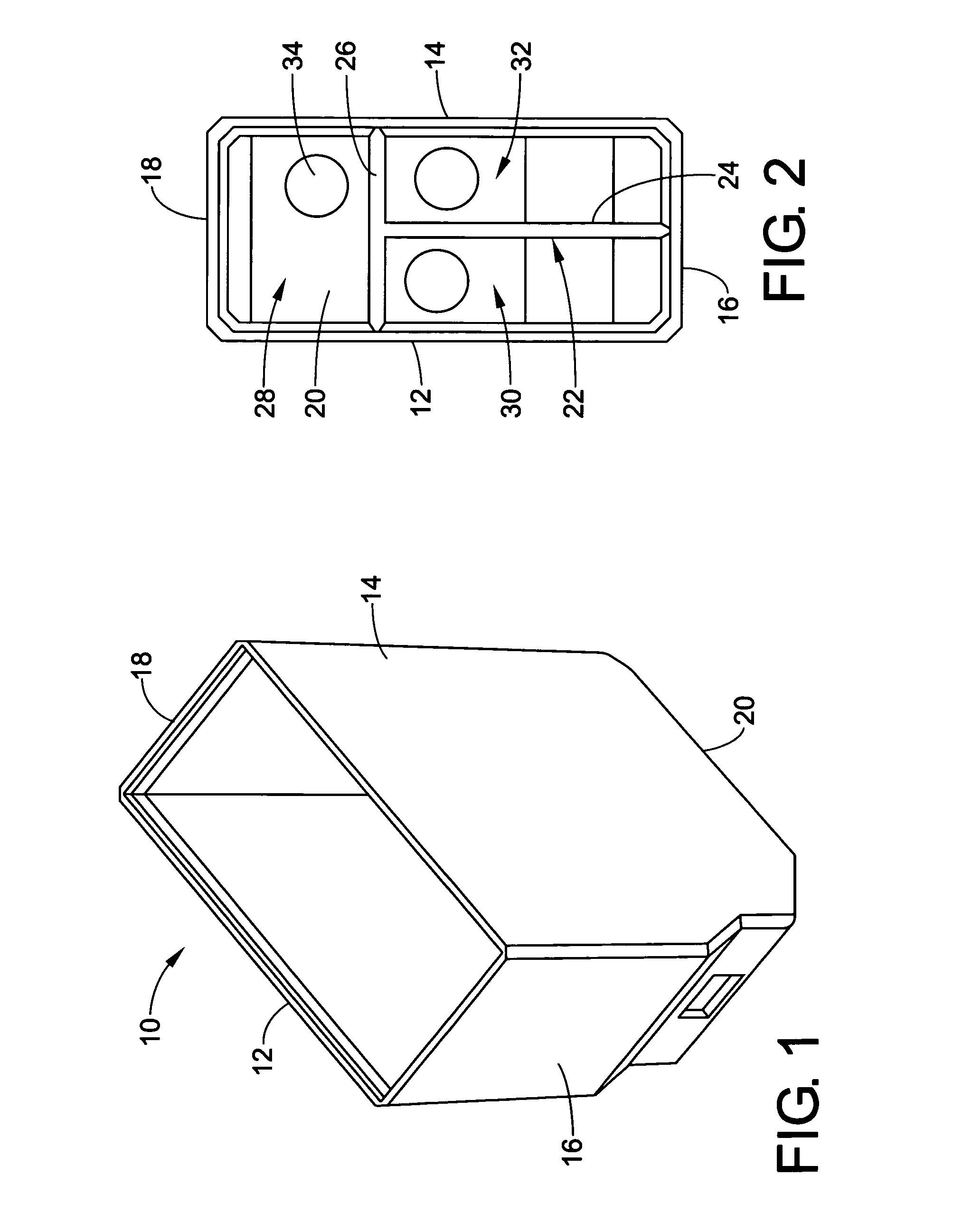
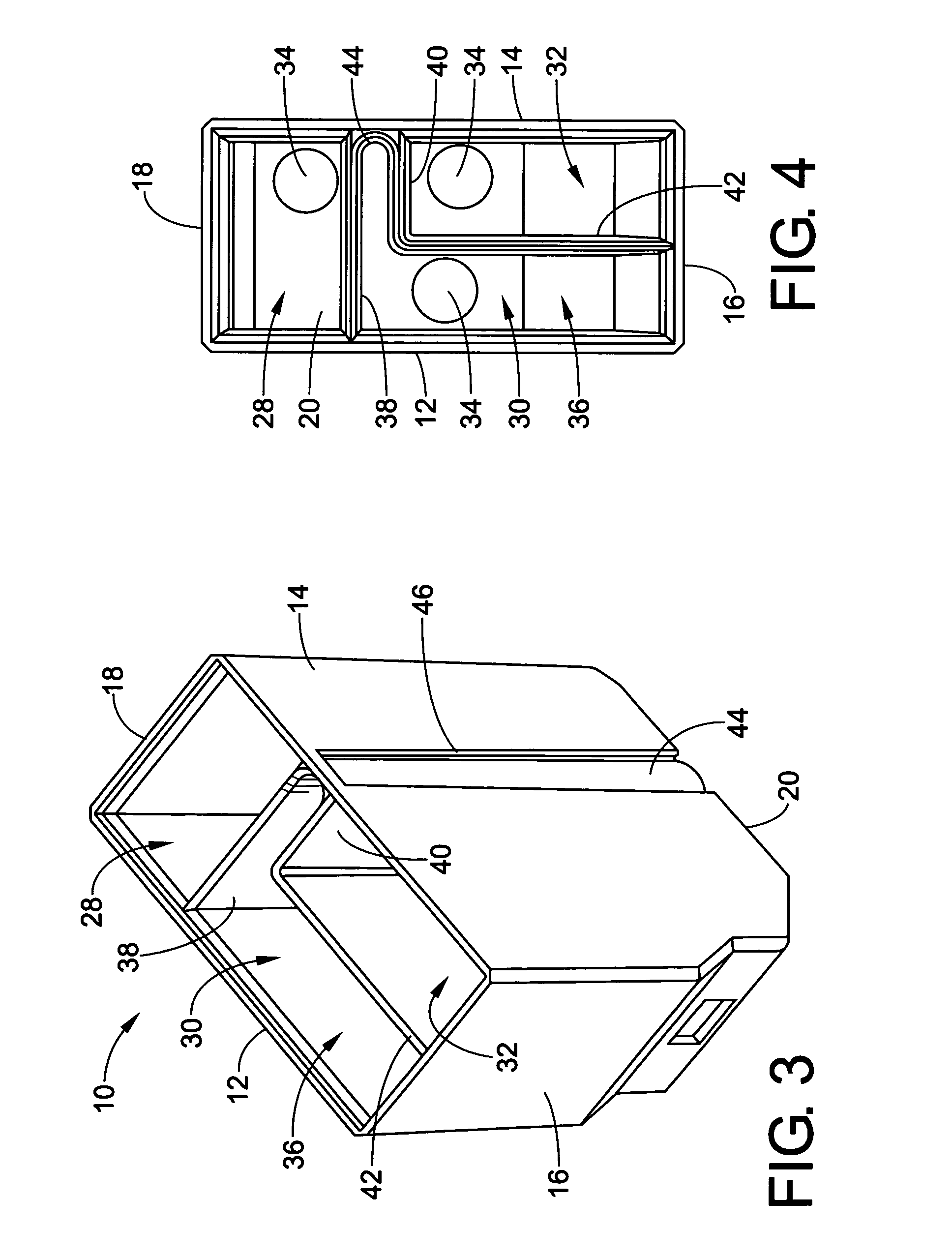
[0016]Referring now in detail to the drawings, wherein the showings are for the purpose of illustrating preferred embodiments of the invention only, and not for the purpose of limiting the invention, an ink container shell 10 is shown in FIGS. 1 and 2 of the drawing which is comprised of a pair of spaced apart side walls 12 and 14, a front wall 16, a rear wall 18 and a bottom wall 20. As shown in FIG. 2, it is well known to provide the interior of the shell with a T-shaped partition 22 defined by a leg 24 and a cross piece 26 which divide the interior of the shell into three ink chambers 28, 30 and 32. The T-shaped profile of partition 22 provides for each of the chambers 28, 30 and 32 to be rectangular in cross-section transverse to the side, front and rear walls of shell ten. Further, it will be appreciated from FIG. 2 that chamber 28 is directly adjacent both chambers 30 and 32 and that each of the chambers 30 and 32 is directly adjacent one another as well as chamber 28. Accordi...


PUM


Abstract

An ink container shell for an ink jet cartridge has spaced apart side walls, a front wall, a rear wall, and a bottom wall, and is provided with a partition structure which divides the interior thereof into three ink chambers, at least one of which has a non-rectangular profile in cross-section transverse to said side, front and rear walls. The partition structures enable varying the volumes of the ink chambers with respect to a given shell exterior profile and enable isolating two the chambers from one another by interposing the third chamber therebetween.

Description

BACKGROUND OF THE INVENTION[0001]This invention relates to the art of ink jet printers and, more particularly, to improvements in the configurations of ink chambers and partitions in the interior of the casing or shell of an ink container for an inkjet cartridge for color printing.[0002]As is known, an inkjet cartridge includes an ink container comprising a shell defined by spaced apart side walls, a front wall, a rear wall, and a bottom wall and, for color printing, the interior of the container is partitioned to define a plurality of chambers, each for a different color ink. Each of the chambers has an outlet port in the bottom wall for communication with a corresponding ink tapping component in a casing receiving the container, and the upper end of the container is closed by a cover which is heat sealed in place following the filling of the chambers with ink.[0003]Heretofore, the partition has been T-shaped in cross-section transverse to the side, front and rear walls whereby, fo...

Claims


Application Information

Patent Timeline
Patent Type & Authority Patents(United States)
IPC IPC(8): B41J2/175
CPCB41J2/17513
Inventor ANDERSEN, STEPHEN A.LENGYEL, DENNIS M.
Owner HITACHI CONSUMER ELECTRONICS CORP
Why Eureka
Try Eureka