Fire-blocking door lock structure

a door lock and fire-blocking technology, applied in the direction of building locks, floor fabrics, constructions, etc., can solve the problems of forming gaps, unable to be completely retracted, and the blocking effect of the door lock could fail, so as to prevent the form of retraction into the latching member

Active Publication Date: 2006-07-04
LIN CHING TIEN
View PDF6 Cites 23 Cited by
  • Summary
  • Abstract
  • Description
  • Claims
  • Application Information

AI Technical Summary

Benefits of technology

[0016]Another objective of the present invention is to provide a fire-blocking door lock structure having a fire-blocking piece that melts at a high temperature such as in a fire, such that the latch body is blocked by a stop piece and cannot be moved, so as to assure lockup of the fire-blocking door and eliminate the possibility that the door lock is accidentally unlatched or opened by someone who is unaware of the fire.
[0017]To achieve the above and other objectives, the fire-blocking door lock structure of the present invention comprises a latching member mounted in a lock casing on a fire-blocking door lock, and an actuation mechanism mounted in the latching member. The actuation mechanism comprises a latch body, a stop piece, a safety latching member, a guide rod, and an actuating piece. The latch body can swing smoothly and is formed with a stop portion. The stop piece prevents retraction of the latch body and is connected to a fire-blocking piece. When the safety latching member abuts against one side of the stop piece, the safety latching member can prevent the latch body from retraction into the latching member. The guide rod enables the latch body to be blocked by the fire-blocking piece. The actuating piece guides both the latch body and the guide rod in motion by an external force.
[0019]Both the safety latching member and the stop piece can pivot or swing smoothly on the latching member. The safety latching member can abut against one side of the stop piece. The fire-blocking piece is formed on an upright portion of the stop piece. The guide rod penetrates the actuating piece to be coupled to the fire-blocking piece connected with the stop piece. As a result, the fire-blocking piece can be pushed to an upper position by forward motion of the guide rod. The latch body pivots and is received within the latching member, allowing the guide rod to abut against the fire-blocking piece and moved toward the latch body. The stop piece, which is coupled to the fire-blocking piece, can move downwards without blocking the stop portion, such that the latch body can be retracted into the latching member to unlatch the fire-blocking door. When the fire-blocking piece melts at a high temperature, the stop piece blocks the stop portion such that the latch body fails to be retracted into the latching member, making the fire-blocking door kept being locked.
[0021]When the fire-blocking door is locked, the safety latching member contacts the doorframe and is retracted backwards. One end of the stop piece is forced to move upwards by elasticity of the spiral spring, while the other end of the stop piece is kept being engaged with the stop portion of the latch body. When the fire-blocking door lock structure is subject to a fire, the fire-blocking piece melts under a high temperature during the fire, allowing the latch body to be blocked from motion by the stop piece, thereby maintaining the lockup status of the fire-blocking door.
[0023]The guide rod can be move upwards by turning clockwise a passive portion of the actuating piece, to allow the guide rod to abut against the fire-blocking piece and move towards the latch body, such that the stop piece, which is coupled to the fire-blocking piece, is moved downwards. As a result, the stop piece would not block the stop portion of the latch body, and accordingly the latch body can be retracted into the latching member by the upward pressure from the passive portion of the actuating piece, thereby releasing the lockup of the fire-blocking door lock structure to open the fire-blocking door.
[0024]When the fire-blocking door lock structure is subject to a fire, the fire-blocking piece coupled to the stop piece melts under a high temperature during the fire. The guide rod fails to abut against the melted fire-blocking piece, making the stop piece moved upwards by the elasticity of the spiral spring. As such, a front end of the stop piece is positioned corresponding to the stop portion of the latch body and thus blocks the stop portion, such that the latch body is prevented form retraction into the latching member. This thereby keeps the fire-blocking door lock structure being latched, so as to prevent the fire-blocking door from being opened by someone who is unaware of the fire and avoid damage from spread of flames.

Problems solved by technology

However, after being used over a long period of time, the structure of the fire-blocking door lock 1 result in a problem wherein a gap is formed between the door and doorframe when the door is latched; consequently, the safety latching member 14 is unable to be entirely retracted into the latching member 15.
This leads to the problem that both the actuating piece 12 and the latch body 11 fail to press against each other, and consequently the latch body 11 becomes loose and is easily retracted into the latching member 15.
In this case, the blocking effect on the fire-blocking door lock could fail.
In summary, a variety of drawbacks in a conventional fire-blocking door lock structure cause the problem of failing to surely latch the fire-blocking door lock 1.
In addition, the structure is unable to cause the fire-blocking door to be securely closed under the lockup condition, or would lengthen the reaction time for effecting the lockup of the door during-a fire.
Moreover, the drawback of failing to maintain the lockup status of the fire-blocking door would seriously affect the fire-blocking effect of the fire-blocking door lock.
It is obvious that the drawbacks of a conventional fire-blocking door lock structure with regard to the fire-blocking operation need to be overcome.

Method used


Image

  • Fire-blocking door lock structure
  • Fire-blocking door lock structure
  • Fire-blocking door lock structure

Examples


Embodiment Construction

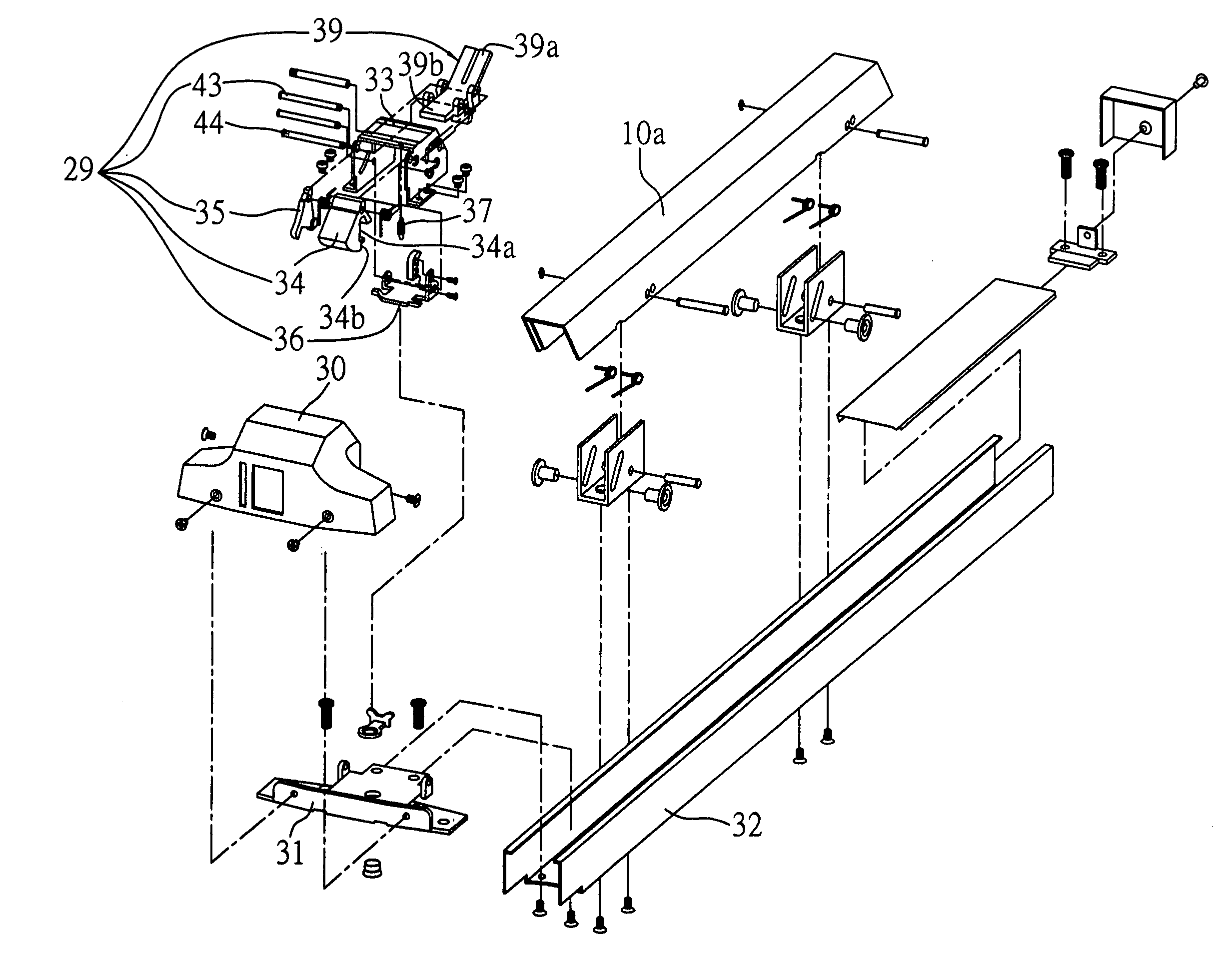
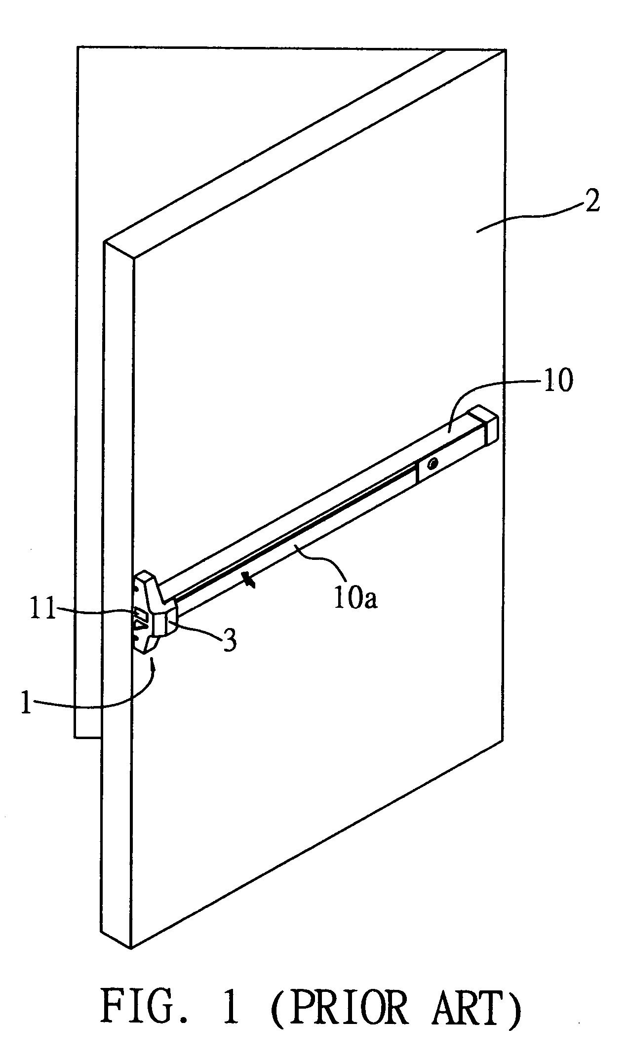
[0033]Referring to FIGS. 4 through 7, a fire-blocking door lock structure according to the present invention comprises a latching member 33 mounted in a lock casing 30 on a fire-blocking door (not shown) and an actuation mechanism 29 installed in the latching member 33. The actuation mechanism 29 comprises a latch body 34, a stop piece 36, a safety latching member 35, a guide rod 43 and an actuating piece 39. The fire-blocking door described in the embodiments of the invention is the same as the conventional fire-blocking door 2 shown in FIG. 1, thereby not further illustrated in the drawings herein.

[0034]The casing 3 is mounted on the fire-blocking door and comprises a push handle 10a and a latch body 34 driven by the push handle 10a. A person can unlatch the door by pressing the push handle 10a that is subsequently forced to contact the actuation mechanism 29. The latching member 33 is coupled to the casing 3 and pivotally connected with the safety latching member 35, the stop pie...


PUM


Abstract

A fire-blocking door lock structure includes a latching member mounted on a fire-blocking door lock and an actuation mechanism mounted in the latching member. The actuation mechanism includes a latch body having a stop portion; a stop piece which prevents retraction of the latch body and is connected to a fire-blocking piece; a safety latching member which prevents the latch body from retraction into the latching member when the safety latching member abuts against the stop piece; a guide rod for allowing the latch body to be blocked by the fire-blocking piece when the safety latching member abuts against the stop piece; and an actuating piece. When the fire-blocking piece melts under a high temperature during a fire, the stop piece blocks the stop portion, such that the latch body cannot be retracted into the latching member, keeping the fire-blocking door locked.

Description

FIELD OF THE INVENTION[0001]The present invention relates to fire-blocking door lock structures, and more particularly, to an improved fire-blocking door lock structure comprising an actuation mechanism having a latch body and a safety latching member, to assure lockup of the fire-blocking door during a fire.BACKGROUND OF THE INVENTION[0002]A conventional fire-blocking door lock structure as shown in FIG. 1 shows that a fire-blocking door lock 1 can be unlatched when a person presses a push handle 10a mounted on a frame member 10 that is horizontally mounted on the center of the fire-blocking door 2. When the push handle 10a is pressed down, a latch body 11 is withdrawn into the inside of a casing 3, unlatching the fire-blocking door lock 1.[0003]To make the structure of the fire-blocking door lock 1 more understandable, the fire-blocking door lock 1 is rotated by 90 degrees such that the back faces downward as shown in FIG. 2. The frame member 10 comprises the push handle 10a mount...

Claims


Application Information

Patent Timeline
Patent Type & Authority Patents(United States)
IPC IPC(8): E05B65/10
CPCE05B65/104Y10S292/65Y10T292/0908Y10T292/0909
Inventor LIN, CHING-TIEN
Owner LIN CHING TIEN
Why Eureka
Try Eureka