Spring-loaded contact connector

Active Publication Date: 2006-07-04
SCHALTBAU GMBH
View PDF10 Cites 32 Cited by
  • Summary
  • Abstract
  • Description
  • Claims
  • Application Information

AI Technical Summary

Benefits of technology

[0020]To achieve a high sealing effect between the spring-loaded contact pins and the slide seal, the seal may be designed as a bellows seal. Bellows seals are normally constructionally connected to the spring-loaded contact pins and follow the axial movement of the spring-loaded contact pins, thereby achieving a particularly high sealing effect.
[0021]In a further variant, the seal is designed as a slide seal and the spring-loaded contact pins are guided in a relatively displaceable manner in the slide seal so that the spring-loaded contact pins slide along the slide seal in sealed fashion when the connector members are joined. The configuration of the seal as a stationary slide seal permits the sealing of the spring-loaded contact mechanism of the first connector member with a single, substantially flat, seal. The slide seal can seal the spring-loaded contact mechanism over the whole displacement path of the spring-loaded contact pins against the penetration of water and other substances from the surroundings. Apart from a saving of costs for the seal, less efforts have to be taken during assembly of the connector members owing to the slide seal.
[0022]Preferably, the slide seal can be produced together with at least a part of the first connector member in a two-component injection molding method. Said production method reduces the numbers of the individual parts needed for the assembly of the spring-loaded contact connector. The two-component injection molding method has the effect that the slide seal can be connected to the jointly produced part of the first connector member, whereby moisture is prevented from penetrating between the slide seal and the simultaneously injected part.
[0023]In a variant of the invention, the slide seal is made from a thermoplastic elastomer (TPE). Thermoplastic elastomers can be easily processed, so that they are particularly suited for injection molding processes. The elastic properties, the dimensional stabil

Problems solved by technology

This telescopic compensation means may be impaired in its operability, especially upon penetration of dirt and moisture during operation, which might also lead to failure of the movement mechanism.
Unfortunately, the c

Method used


Image

  • Spring-loaded contact connector
  • Spring-loaded contact connector
  • Spring-loaded contact connector

Examples


Embodiment Construction

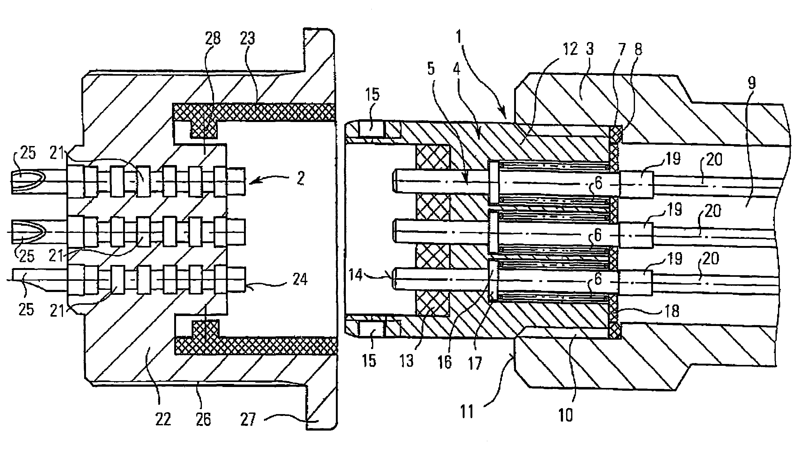
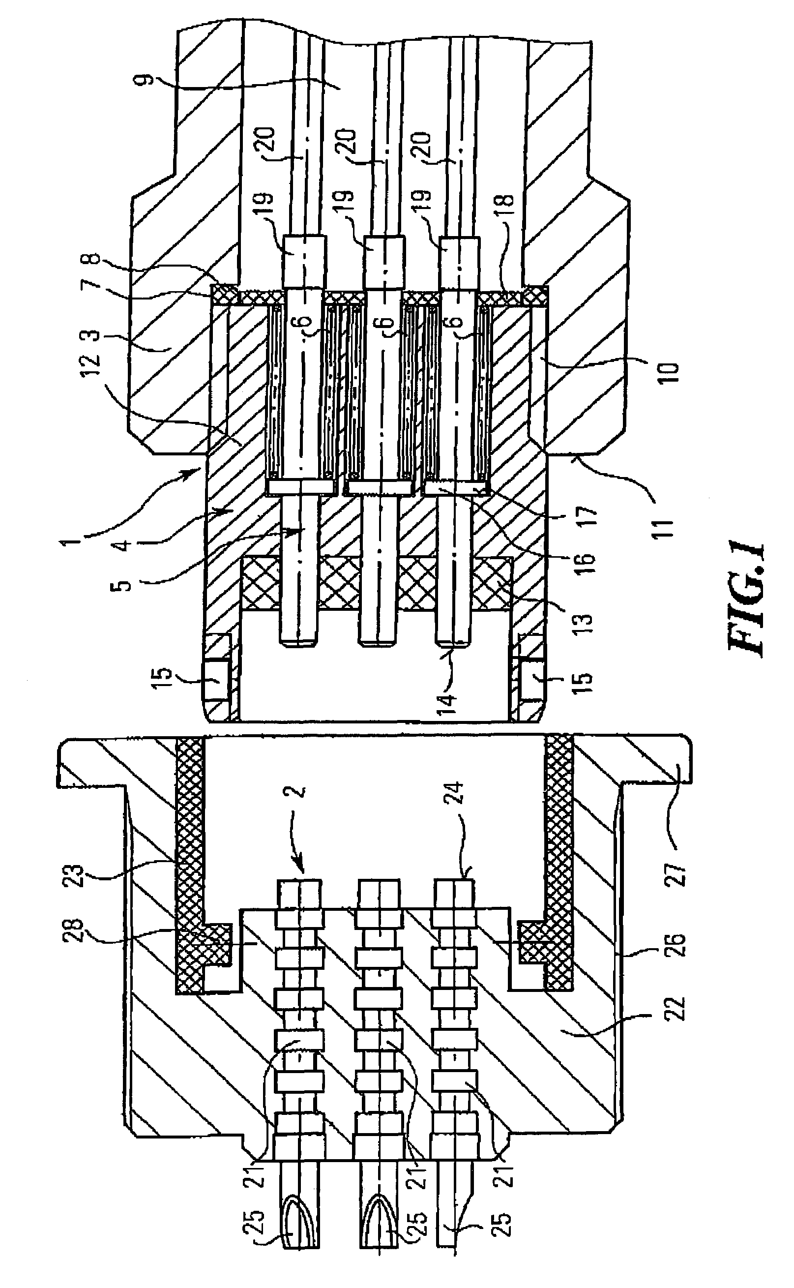
[0031]FIG. 1 is a schematic view showing an inventive spring-loaded contact connector composed of two joinable connector members 1, 2, in the non-joined state. The first connector member 1, which is shown at the right side of FIG. 1, is designed as a plug and the connector member 2, which is shown at the left side of FIG. 1, as a flange socket. Said connector members 1, 2 can be joined and locked by means of a bayonet lock.

[0032]The first connector member 1, which is designed as a plug, consists of a contact element 4 arranged in a plug housing 3, in which integral cylindrical spring-loaded contact pins 5 are arranged in an axially displaceable manner against the restoring force of compression springs 6. The plug housing 3 comprises an inner surrounding groove 7 in which a sealing ring 8 is arranged for sealing the interior 9. The contact element 4 is connected to the plug housing 3, especially screwed or glued, in a connection area 10 which is arranged between the surrounding groov...


PUM


Abstract

The present invention relates to a spring-loaded contact connector comprising two joinable connector members of which at least a first connector member comprises a plurality of spring-loaded contact pins that are supported in an axially displaceable manner in the connector member against a restoring force, wherein the first connector member comprises a connection area for establishing a firm electrical connection, and the connection area includes a compensating means for the axial displacement path of the spring-loaded contact pins

Description


Claims


Application Information

Patent Timeline
Owner SCHALTBAU GMBH
Why Eureka
Try Eureka