
Charge pump clock for non-volatile memories

a charge pump and non-volatile memory technology, applied in pulse manipulation, pulse technique, instruments, etc., can solve the problems of insufficient read voltage supplied by the charge pump, inability to regulate voltage, read error, etc., and achieve the effect of less power consumption, less cost and less power

Active Publication Date: 2006-07-04
ATMEL CORP
View PDF3 Cites 16 Cited by
  • Summary
  • Abstract
  • Description
  • Claims
  • Application Information

AI Technical Summary

Benefits of technology

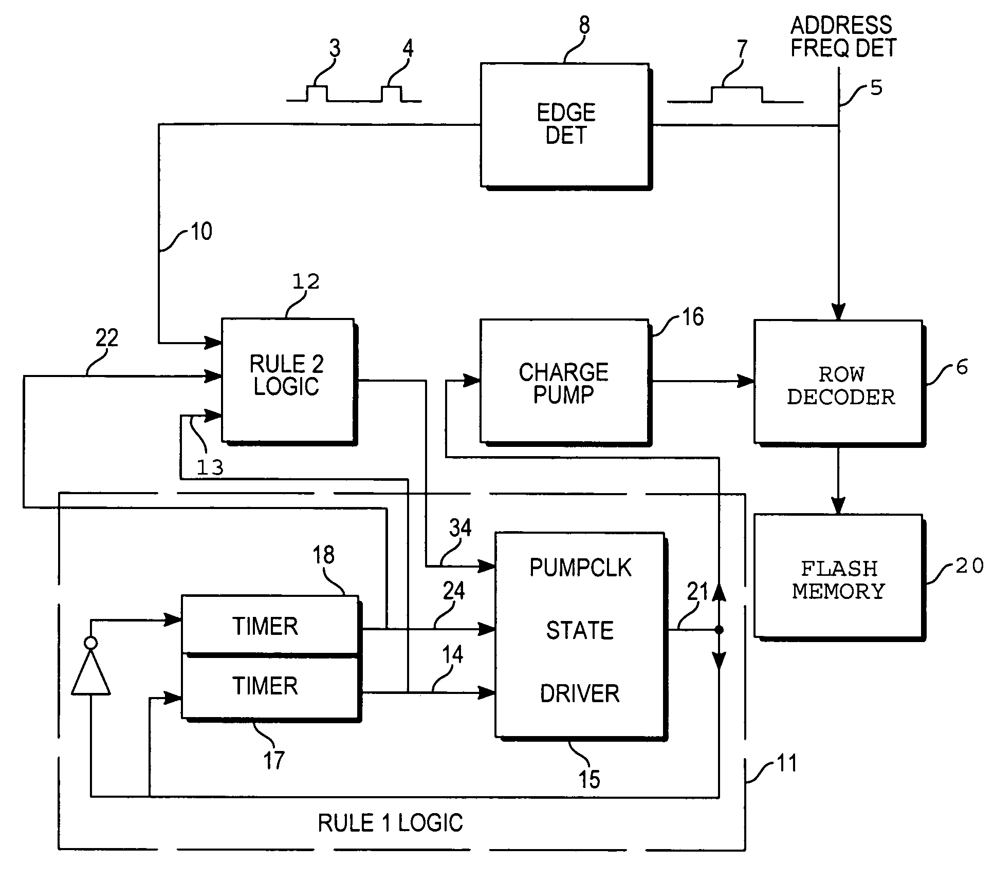
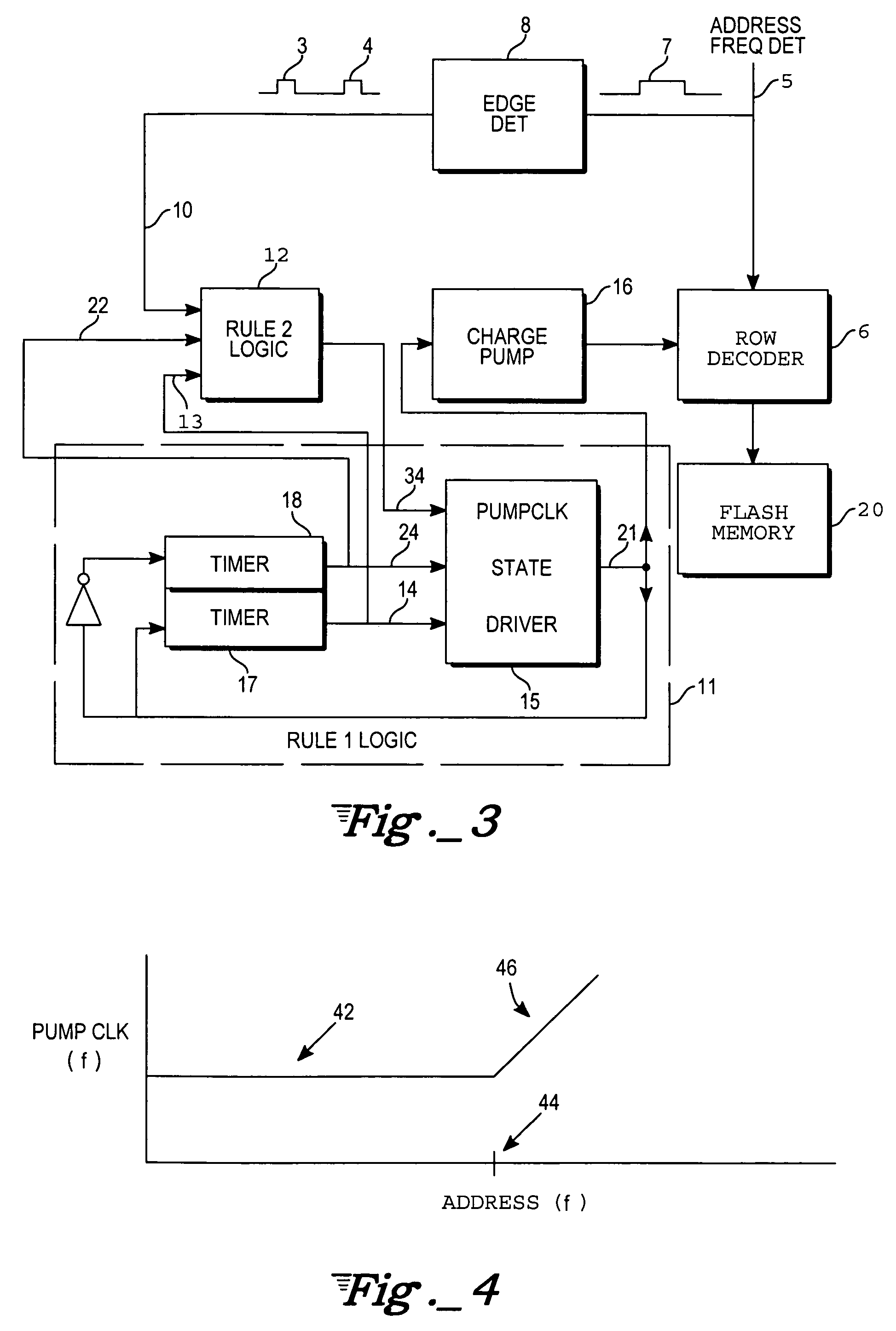
[0019]The present invention provides a pump clock with a variable frequency and duty cycle that depends on the read frequency and duty cycle. With this approach, the charge pump clock edges occur in direct proportion to the load current. The problem of having a fixed clock source with wide frequency variation is eliminated and thus, the charge pump can be smaller, less expensive, and consume less power than with conventional techniques.

Problems solved by technology

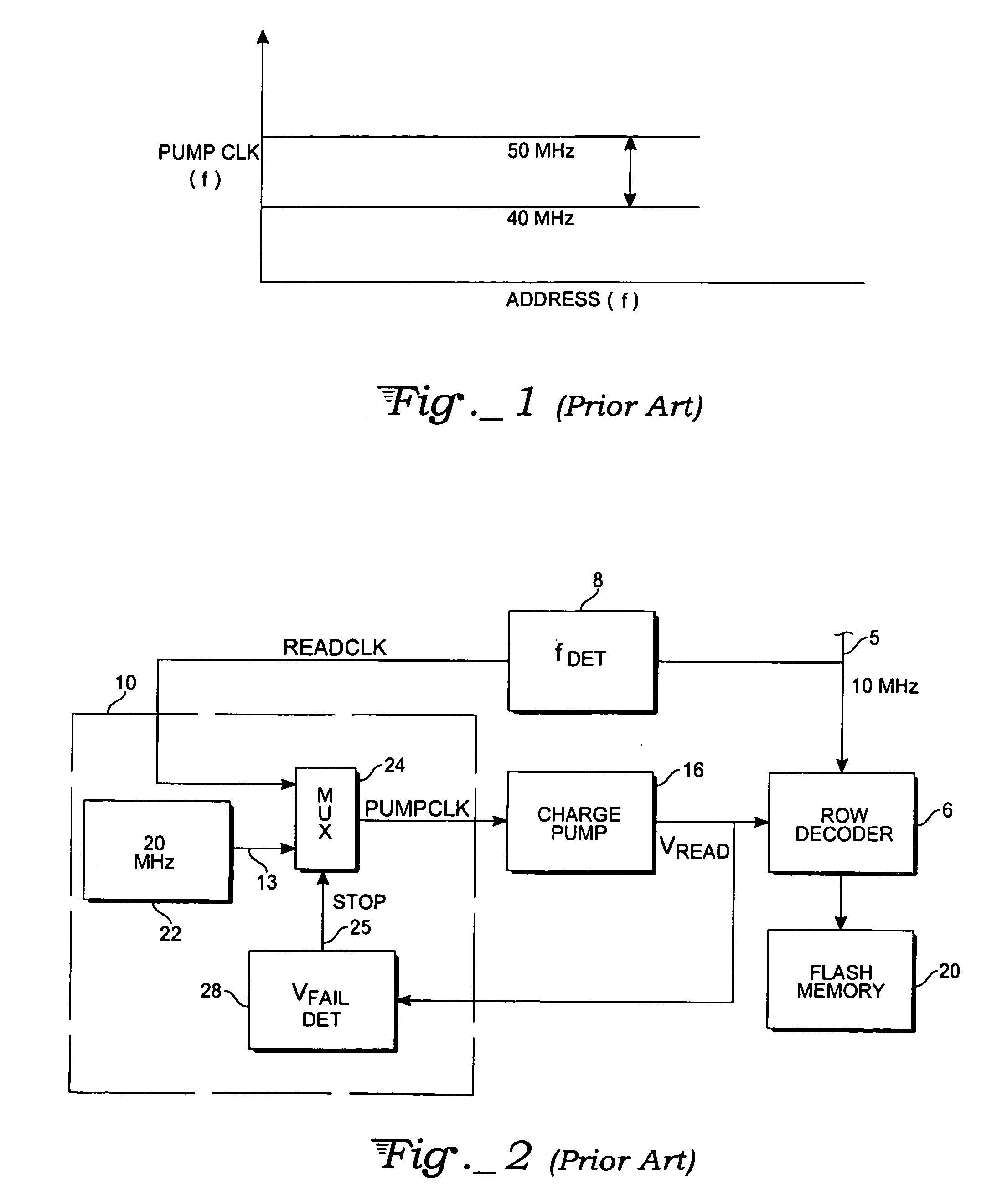
A problem with conventional charge pumps associated with non-volatile memories is unstable voltage regulation because of fluctuating current demand.
A problem arises in the case of memories operating at low VCC.
For instance, with a supply voltage VCC of 2.5 V, all the cells with a threshold voltage VTH close to this value conduct little or no current, so that the cell is considered programmed, thus resulting in a read error.
Where address transitions occur at much higher frequencies than the maximum allowable, the read voltage supplied by the charge pump will be inadequate, i.e. below an established failure voltage, VFAIL.

Method used


Image

  • Charge pump clock for non-volatile memories
  • Charge pump clock for non-volatile memories
  • Charge pump clock for non-volatile memories

Examples


example no.1

EXAMPLE NO. 1

[0046]FIG. 6A depicts readclk signal 162 cycling at a frequency that is higher than FMIN=1 / (2×TD), whereas the duty cycle of readclk is much less than 50%:

readclk_frequency≧FMIN=1 / (2×TD)

and

readclk_duty_cycle<50%  (9)

[0047]The usage of the charge pump clock 100 of FIG. 5 in the charge pump instead of the usage of the conventional oscillator results in generating of the pumpclk signal 164 for the wordline pump which has the same frequency as the frequency of readclk, but with improved duty cycle:

pumpclk_frequency=readclk_frequency

and

pumpclk_duty_cycle>readclk_duty_cycle.  (10)

example no.2

EXAMPLE NO. 2

[0048]FIG. 6B depicts readclk signal 172 cycling at a frequency that is higher than FMIN=1 / (2×TD), whereas the duty cycle of readclk is much more than 50%:

readclk_frequency≧FMIN=1 / (2×TD)

and

readclk_duty_cycle>50%  (11)

[0049]The usage of the charge pump clock 100 of FIG. 5 in the charge pump instead of the usage of the conventional oscillator results in generating of the pumpclk signal 174 for the wordline pump which has the same frequency as the frequency of readclk, but with improved duty cycle:

pumpclk_frequency=readclk_frequency

and

pumpclk_duty_cycle

example no.3

EXAMPLE NO. 3

[0050]FIG. 6C depicts readclk signal 182 that is not cycling at all. However, the charge pump clock 100 of FIG. 5 will generate pumpclk signal 184 for the wordline pump at the frequency FMIN=1 / (2×TD)

readclk_frequency=0;

pumpclk_frequency=FMIN=1 / (2×TD).  (13)


PUM


Abstract

A charge pump clock for a memory device wherein pump clock signals are generated at an adaptive rate. The circuit of the present invention generates clock edges at a minimum of TD seconds apart so long as address transitions do not exceed a pre-determined limit. However, if address changes are occurring more frequently than this limit, i.e., 1 / (2*TD), then clock edges will be generated at a rate that is proportional to the rate of address changes, where TD is approximately half of the address period. Two logic rules are implemented in hardware or equivalent software to make the clock signal adjustments.

Description

TECHNICAL FIELD[0001]The invention relates to a charge pump clock used in a non-volatile memory device, and more particularly, to an accurate clock control circuit for a charge pump used with a non-volatile memory.BACKGROUND ART[0002]A problem with conventional charge pumps associated with non-volatile memories is unstable voltage regulation because of fluctuating current demand. The fluctuation arises because current demanded from a charge pump used in non-volatile memories is proportional to the frequency at which data is read from the memory. More specifically, address changes cause charge to be drawn from the charge pump that must be replenished by clocking the pump.[0003]Clocking of charge pumps is done at a frequency that can exhibit some variability due to process variables, temperature, voltage changes, but is generally uniform. This is illustrated in FIG. 1 where pump clock frequency is shown as a function of address transitions or address frequency. The charge pump is assu...

Claims


Application Information

Patent Timeline
Patent Type & Authority Patents(United States)
IPC IPC(8): H03K5/26H03K7/08G11C5/14G11C11/34
CPCG11C5/145
Inventor WICH, MATHEW T.
Owner ATMEL CORP
Learn More