Bi-directionally driven forward converter for neutral point clamping in a modified sine wave inverter
What is AI technical title?
AI technical title is built by Patsnap AI team. It summarizes the technical point description of the patent document.
a forward converter and neutral point clamping technology, applied in the direction of electric variable regulation, process and machine control, instruments, etc., can solve the problems of high transformer loss, high quantity of primary turns, and high power dissipation in the active device, so as to achieve low internal resistance, increase inductance, and high inductance
Inactive Publication Date: 2006-07-04
DAMATO JAMES
View PDF6 Cites 14 Cited by
Summary
Abstract
Description
Claims
Application Information
AI Technical Summary
This helps you quickly interpret patents by identifying the three key elements:
Problems solved by technology
Method used
Benefits of technology
Benefits of technology
[0012](a) to provide a first order approximation of a sine wave for the purpose of driving a diverse range of load impedances without the adverse side effects of load generating spikes at applied voltage transitions
[0020]In accordance with the present invention, the half bridge converter and its developing of a modified sine wave is susceptible to damage as a result of transients generated by an inductive load. Making use of a bi-directional high frequency forward converter for output neutral point clamping ensures the waveshape in the time domain for the first order approximation of the output sine wave.
Problems solved by technology
Pending the input voltage, the quantity of primary turns was usually very high and transformer losses were also typically high, especially when driven into saturation.
Having high peak currents, the power dissipation in the active devices could grow quickly.
A problem associated with these types of self-oscillating circuits was that any variation at the input voltage would be directly transformed to the output by a factor of the turns ratio thereby producing a somewhat poor line regulation.
Attempting to regulate the input voltage prior to the transformer would typically yield undesirable losses and would also be an impeding factor for producing maximum output power.
This in itself could be damaging to the output of the inverter or input of the interfacing equipment.
A few patents have been composed to address this problem since inductive loads could become destructive to the drive circuitry, the load itself, and generate unnecessary higher order harmonics.
A modified sine wave inverter that produces a first order wave shape of a sine wave is a precedent to the PWM inverter however lacking any type of filtering and when subjected to inductive loads, could result with damaging effects to both the drive and the load.
Method used
Image
Click on the blue label to locate the original text in one second.
Reading with bidirectional positioning of images and text.
Examples
Embodiment Construction
—FIGS. 1, 2, AND 3—PREFERRED EMBODIMENTS
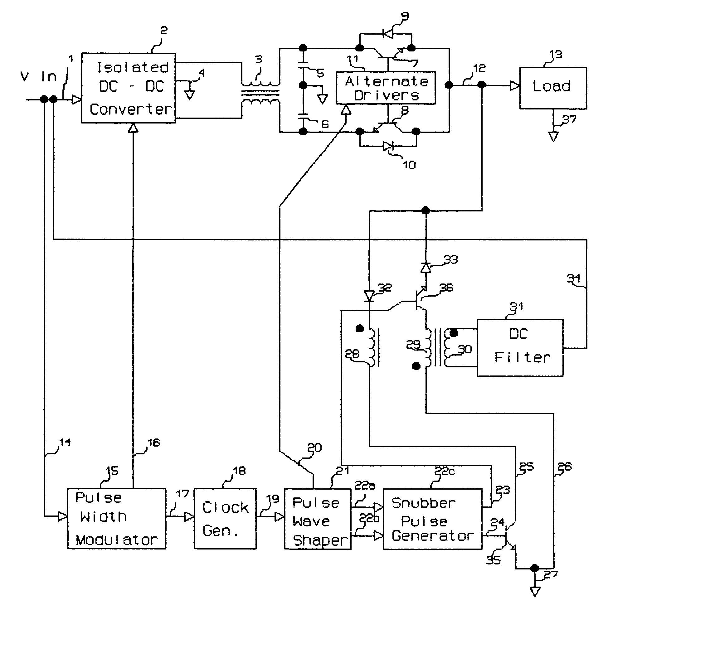
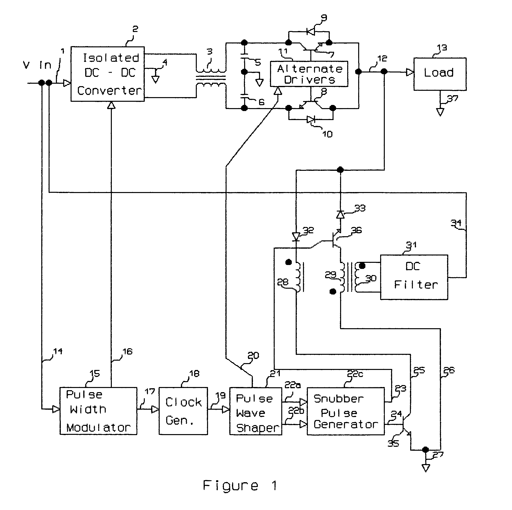
[0049]The functional elements of the basic modified sine wave converter are shown in the block diagram of FIG. 1. Although this invention applies to the bi-directional forward converter for neutral point clamping used within, it is felt necessary to address components used for the drive that support the converter in addition to the output for which the converter interfaces. This will ultimately yield a more thorough understanding of its operation.
[0050]A source voltage 1 is applied to the input of the isolated dc—dc converter 2 which is supported by a pulse width modulator 15 having its own internal oscillating frequency. The source voltage I is also applied to the pulse width modulator 15 via line 14 to operate its internal circuitry. The output of the isolated dc—dc converter 2 is a differential voltage of approximately 280–330 vdc with center tap 4 connected to the return of the modified sine wave output and the return of the input source v...
PUM
Abstract
A bi-directionally driven forward converter for neutral point clamping in a modified sine wave inverter maintains wave shape integrity when the half bridge output is subjected to loads of varying impedances. This bi-directionally driven forward converter is supported by a dual primary coupled to a common secondary transformer of which both primaries are wound in opposition to each other. A high frequency snubbing pulse generator outputs a series of pulses coincidental with the turn off of the half bridge power transistors and pending the polarity of the modified sine wave output would permit current flow through either of the two primary windings. Given that the transformer secondary voltage is ultimately rectified, filtered, and tied to the input of the inverter itself, reflects back an impedance to the primary winding that is non-dissipative. The series of pulses emanating from the snubbing pulse generator ultimately suppresses any reverse voltage transients developed as a result of the load during the dead time of the modified sine wave output thereby maintaining the output wave shape under the most adverse applied conditions.
Description
REFERENCES CITED[0001]U.S. Pat. No.DateInventor(s)6,108,220August 2000Franke6,016,095January 2000Herbert5,373,433December 1994Thomas5,258,902November 1993Lindbery5,130,917July 1992Shekhawat5,091,841February 1992Tuusa4,961,129October 1990Shekhawat4,903,188February 1990Madhavan, et al.4,862,342August 1989Dhyanchand, etal.4,849,873July 1989Vanderhelst4,802,078January 1989Hill4,706,177November 1987Josephson4,670,828June 1987Shekhawat, et al.4,639,849January 1987Norworolski, et al.4,614,998September 1986Rilly4,602,322August 1986Henderson4,564,895January 1986Glennon4,493,017January 1985Kammiller, et al.4,443,841April 1984Mikami, et al.4,339,791July 1982Mitchell4,128,868December 1978Gamble4,063,306December 1977Perkins, et al.3,432,737March 1969Hunter, et al.3,286,155November 1966Corey3,207,974September 1965McMurray3,125,726March 1964CliftonFEDERALLY SPONSORED RESEARCH[0002]Not ApplicableSEQUENCE LISTING OR PROGRAM[0003]Not Applicable[0004]1. Field of the Invention[0005]This invention relat...
Claims
Application Information
Patent Timeline
Application Date:The date an application was filed.
Publication Date:The date a patent or application was officially published.
First Publication Date:The earliest publication date of a patent with the same application number.
Issue Date:Publication date of the patent grant document.
PCT Entry Date:The Entry date of PCT National Phase.
Estimated Expiry Date:The statutory expiry date of a patent right according to the Patent Law, and it is the longest term of protection that the patent right can achieve without the termination of the patent right due to other reasons(Term extension factor has been taken into account ).
Invalid Date:Actual expiry date is based on effective date or publication date of legal transaction data of invalid patent.

