
Punching device, sheet processor having the punching device, and image forming apparatus having the punching device

a technology of punching device and punching mechanism, which is applied in the direction of digital marking by punching, digitally marking record carriers, instruments, etc., can solve the problems of complex operation mechanism, inability to meet the demand by using, and inability to punch holes in a member smoothly and quickly, so as to achieve the effect of quick punching operation and reliable stopping of the operating member

Inactive Publication Date: 2006-07-11
CANON KK
View PDF14 Cites 14 Cited by
  • Summary
  • Abstract
  • Description
  • Claims
  • Application Information

AI Technical Summary

Benefits of technology

The present invention provides a punching device that can smoothly punch holes and quickly change the number of holes to be punched. The device includes a die member with multiple die holes, punch members that can be advanced into the die holes to punch holes in a member to be punched, and an operating member that can be moved to selectively cause the punch members to advance. The device also includes position detection means for detecting the position of the operating member and operation control means for controlling the drive means based on the detection. The device can be used in a punching device, a sheet processor, and an image forming apparatus. The technical effects of the invention include improved punching efficiency, flexibility, and speed.

Problems solved by technology

Conventional punching devices, however, have a complicated mechanism for operating each punch and are therefore incapable of punching holes in a member smoothly and quickly.
It is not possible to satisfy the demand by using any of the conventional punching devices since each conventional punching device has only punches and dies corresponding to the number of holes to be punched in a member.

Method used


Image

  • Punching device, sheet processor having the punching device, and image forming apparatus having the punching device
  • Punching device, sheet processor having the punching device, and image forming apparatus having the punching device
  • Punching device, sheet processor having the punching device, and image forming apparatus having the punching device

Examples


Embodiment Construction

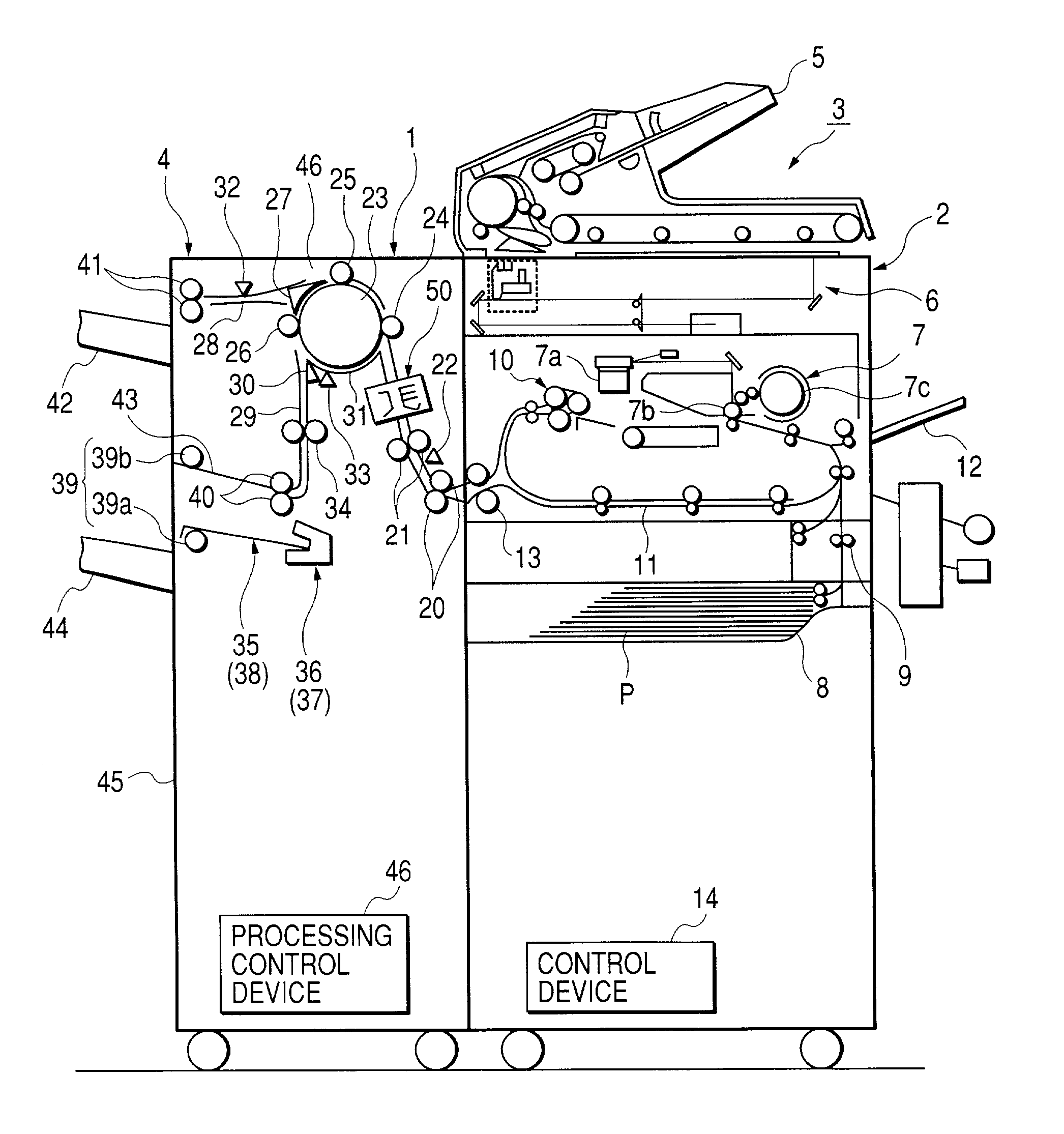
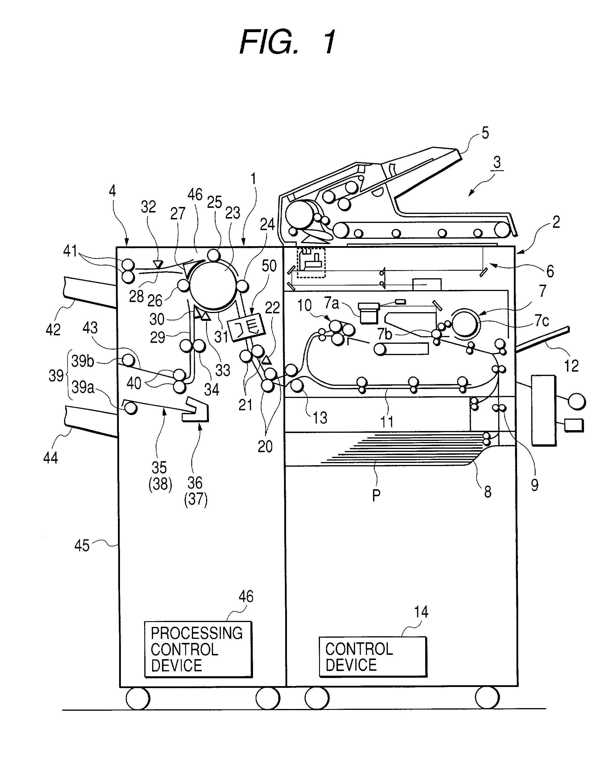
[0049]An image forming apparatus which represents an embodiment of the present invention, which is, typically, a printer, and which includes a punching device and a sheet processor will be described with reference to the accompanying drawings.

[0050]The present invention will be described below with respect to a case of punching holes in a sheet. However, the punching device of this embodiment is capable of punching holes a thin member (member which should be punched), e.g., a board or a plate such as a wooden board or an iron plate, or a sheet of some material. Therefore punching with the punching device of the present invention is not limited to punching on a sheet only.

[0051]The punching device is used singly or as a portion of an apparatus with which a sheet is handled, i.e., in a state of being incorporated in the apparatus. The apparatus with which a sheet is handled is, for example, a sheet processor for binding or folding punched sheets or an image forming apparatus for formi...


PUM

PropertyMeasurementUnit
timeaaaaaaaaaa
areaaaaaaaaaaa
speedaaaaaaaaaa

Abstract

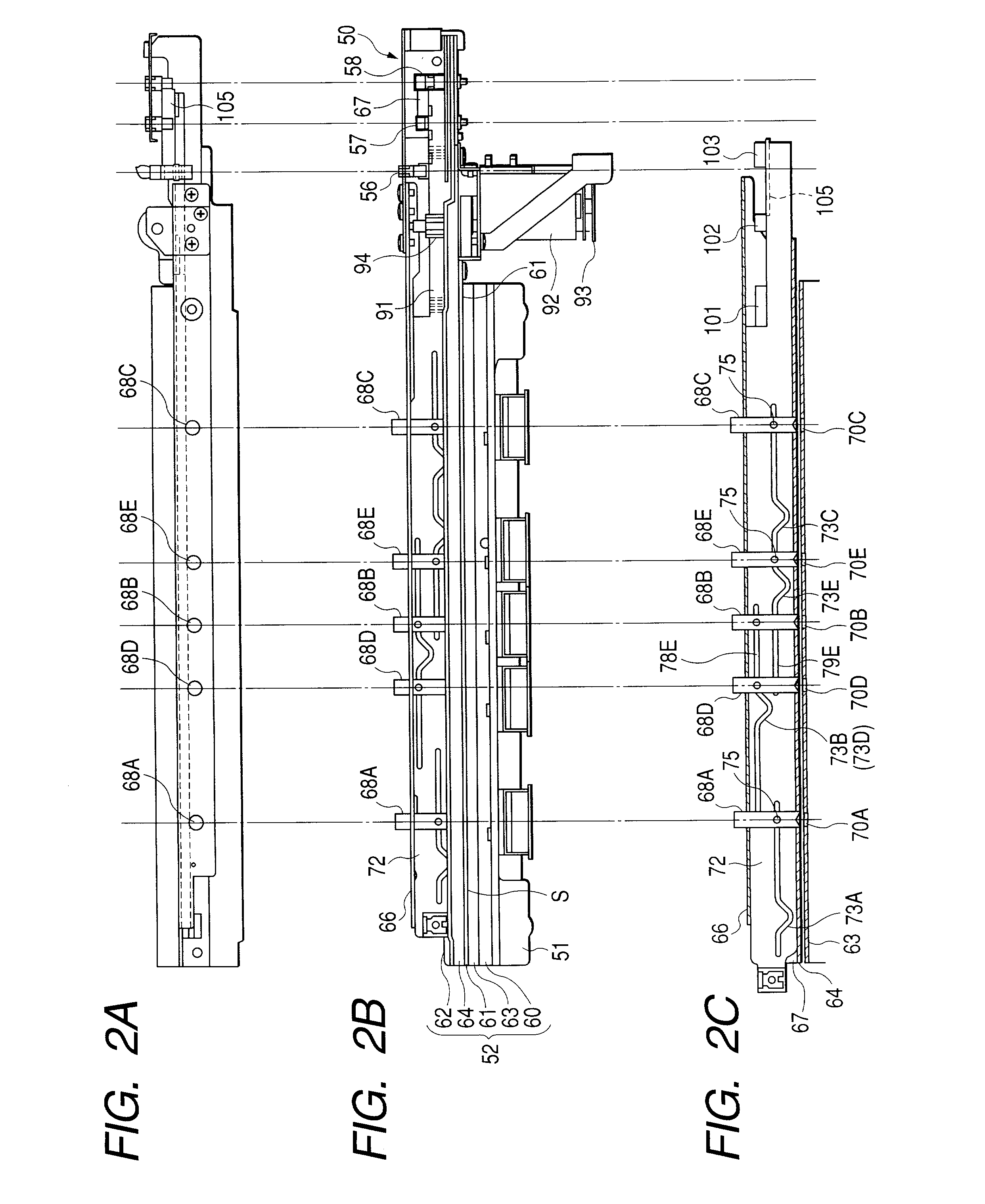
There is provided a punching device including: a die member having a plurality of die holes formed therein; a plurality of punch members which are caused to advance into the die holes to punch holes in a member to be punched; an operating member having cam portions formed along a direction intersecting the direction of advancement of the punch members, the operating member being moved along the direction intersecting the direction of advancement of the punch members to cause by a conversion function of the cam portions the punch members to advance into the die holes; and a drive unit for selectively causing advancement of the plurality of punch members by changing the direction of movement of the operating member. In the punching device, each of the cam portions has a straight groove and a cam groove for performing the conversion function, and when the operating member is moved in one of opposite directions, at least one of the cam grooves of the cam portions acts on one of the punch members to selectively cause the same to advance.

Description

BACKGROUND OF THE INVENTION[0001]1. Field of the Invention[0002]The present invention relates to a punching device for punching holes in a thin member, e.g., a board or a plate such as a wooden board or an iron plate, or a sheet of some material, a sheet processor having the punching device provided in its main body, and an image forming apparatus also having the punching device provided in its main body.[0003]2. Related Background Art[0004]Conventionally, punching devices have been used singly or as a component in a state of being incorporated in an apparatus with which a thin member to be punched is handled.[0005]For example, an application of a punching device in a sheet processor for binding or folding punched sheets is known. The punching device is used in a state of being incorporated in the main body of the sheet processor. An application of a punching device in an image forming apparatus such as a copying machine, a laser beam printer, a facsimile machine, or a combination o...

Claims


Application Information

Patent Timeline
Patent Type & Authority Patents(United States)
IPC IPC(8): B26F1/04B26D7/01B26D5/16B65H35/02B65H37/04
CPCB26D5/16B26F1/04B26F1/0092G03G2215/00818Y10T83/943Y10T83/8831Y10T83/8843Y10T83/8727
Inventor YAGINUMA, MASATOSHISUGITA, SHIGERUMORISHIGE, YUJIFUKAZU, YASUOMURATA, MITSUSHIGEOKAMOTO, KIYOSHI
Owner CANON KK
Learn More