Adjustable bracket for securing an electrical box to a stud

a technology for fixing brackets and electrical boxes, which is applied in the direction of coupling device connections, curtain suspension devices, instruments, etc., can solve the problems of not being able to correctly position the bracket on the stud, complicating the construction process, and inefficient and time-consuming endeavors, so as to reduce the number of different brackets in inventory, facilitate the positioning of the bracket, and facilitate the securing of the brack

Active Publication Date: 2006-07-11
HUBBELL INC
View PDF21 Cites 53 Cited by
  • Summary
  • Abstract
  • Description
  • Claims
  • Application Information

AI Technical Summary

Benefits of technology

[0008]Another objective of the present invention is to provide an improved adjustable bracket adapted to be securable to supports of various sizes, thereby reducing the number of different brackets in inventory.
[0009]A further objective of the present invention is to provide an improved bracket having an adjustable member to facilitate securing the bracket to supports of various sizes.
[0010]A further objective of the present invention is to provide a centerline on the bracket corresponding to marked indicia on the support to facilitate positioning the bracket on the support.

Problems solved by technology

This results in an inefficient and time consuming endeavor and further complicates the construction process.
Another problem with existing electrical box brackets is not being able to correctly position the bracket on the stud.
Existing electrical box brackets do not have openings that allow an installer to align the bracket with indicia marked on the stud to correctly position the bracket on the stud.
This results in electrical boxes not being in proper positions when secured to the bracket.
The brackets must then be remounted on the stud, thereby resulting in an inefficient and time consuming installation process.
Another problem with existing electrical box brackets is that there are insufficient weld projections on the brackets to ensure an adequate weld exists between the bracket and the electrical box, thereby compromising the integrity of the weld.
This problem is further complicated by the numerous different electrical box brackets that are used in the construction process.
Different electrical boxes have different knockout patterns, which often results in weld projections being located in a knockout so that it may not be used to create a weld joint between the electrical box and the bracket.

Method used


Image

  • Adjustable bracket for securing an electrical box to a stud
  • Adjustable bracket for securing an electrical box to a stud
  • Adjustable bracket for securing an electrical box to a stud

Examples


Embodiment Construction

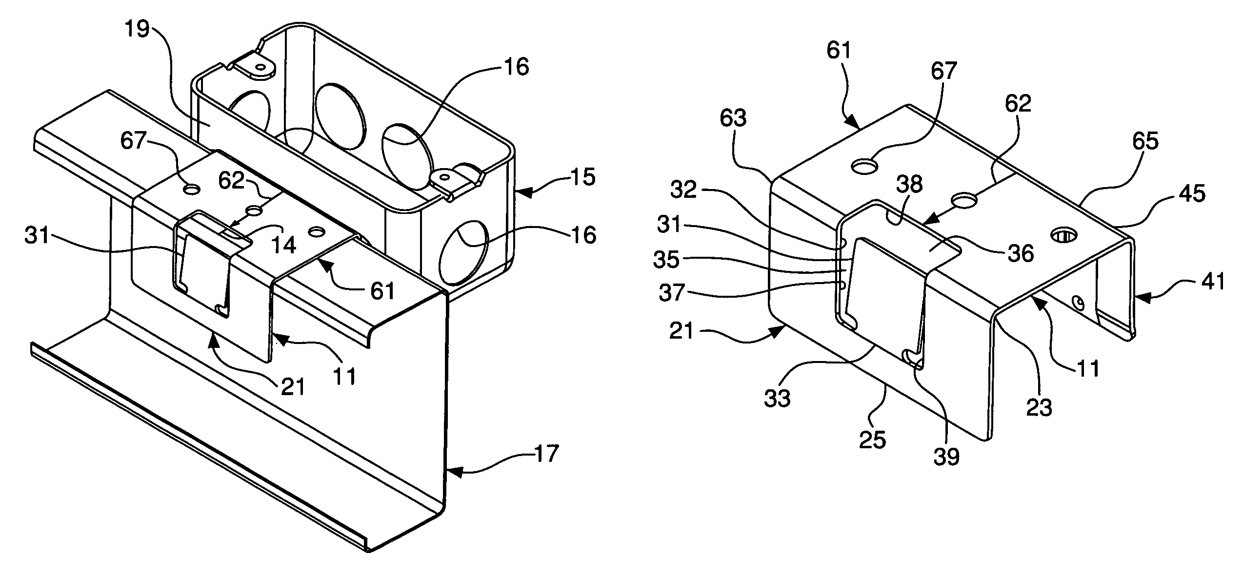
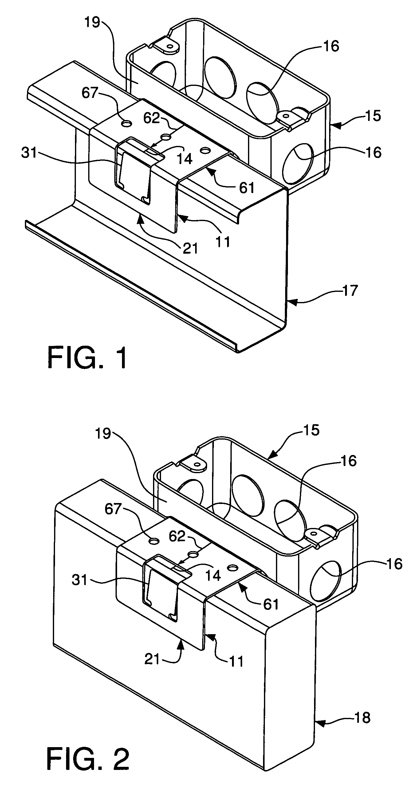
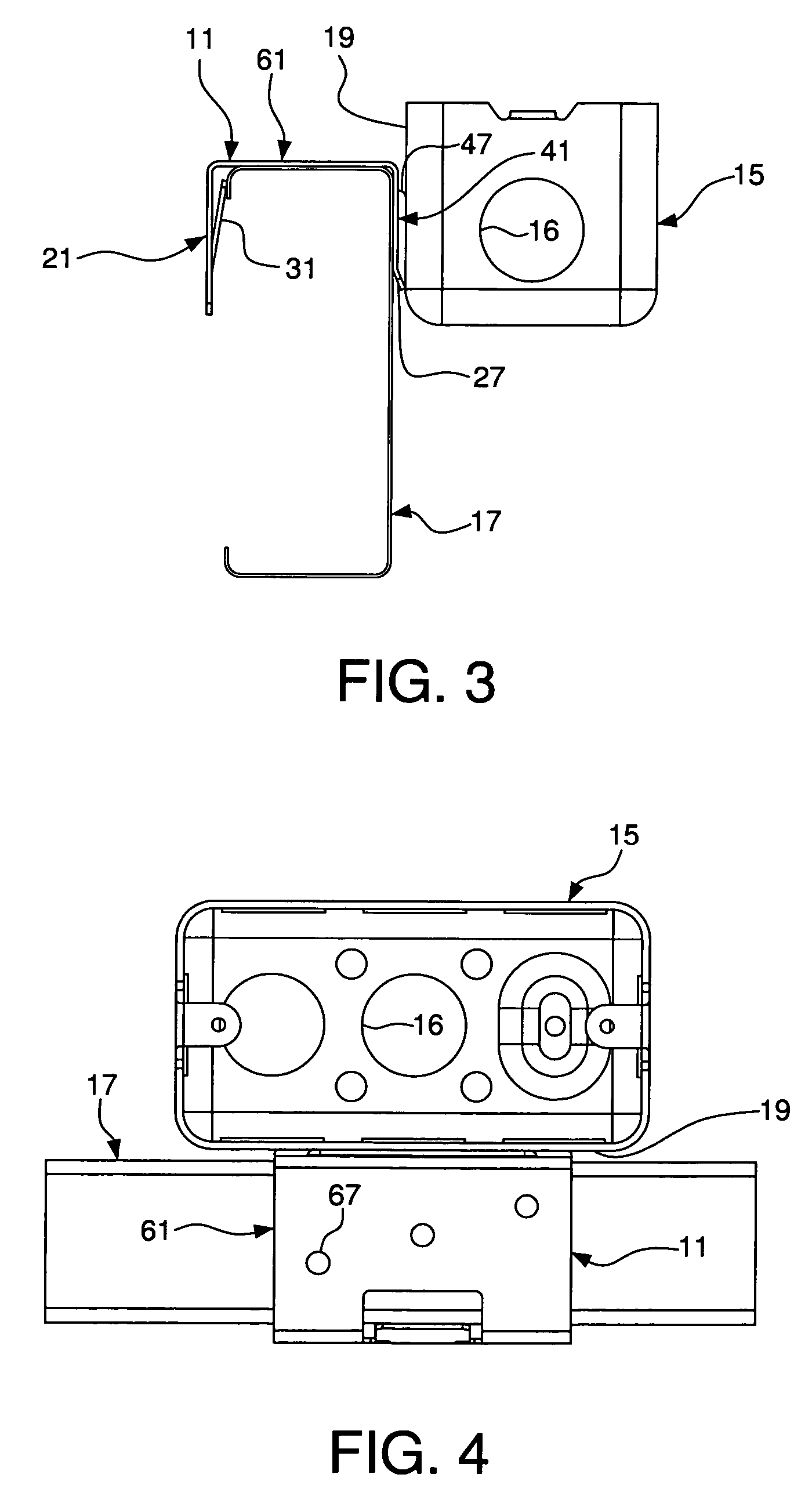
[0025]As shown in FIGS. 1–10, the present invention relates to an electrical box bracket 11 having an adjustable, or securing, member 31 to facilitate securing the bracket to supports of various sizes, such as a metal stud 17 or a wood stud 18. The electrical box bracket 11 has a first leg 21 and a second leg 41 that are substantially parallel. A third leg 61 connects the first leg 21 to the second leg 41. A cut-out 32 extends from the first leg 21 onto the third leg 61. The adjustable member 31 is formed by the cut-out 32 to facilitate securing the bracket 11 to the support. A centerline 62 on the third leg 61 of the bracket 11 is adapted to be aligned with corresponding indicia 14 on the support. The support indicia 14 is visible through the cut-out 32 to facilitate positioning the bracket 11 on the support. A plurality of weld projections 42 and 44 on the second leg 41 facilitate securing a variety of different electrical boxes 15 to the electrical box bracket 11.

[0026]The third ...


PUM


Abstract

An electrical box bracket has an adjustable member to facilitate securing the bracket to supports of varying sizes. The bracket has first and second legs that are connected by a third leg. A cut-out extends from the first leg onto the third leg. The adjustable member is formed by the cut-out to facilitate securing the bracket to the support. A centerline on the third leg of the bracket is adapted to be aligned with corresponding indicia on the support. The support indicia is visible through the cut-out to facilitate positioning the bracket on the support. A plurality of weld projections on the second leg facilitate securing a variety of different electrical boxes to the electrical box bracket.

Description

FIELD OF THE INVENTION[0001]The present invention relates to an adjustable bracket for securing an electrical box to a support. More particularly, the present invention relates to a bracket having an adjustable member to secure an electrical box to studs of different sizes. Still more particularly, the present invention relates to a bracket having an adjustable member to secure an electrical box to either a metal or wood stud, the adjustable member being formed by a cut-out located in two different legs forming the bracket.BACKGROUND OF THE INVENTION[0002]Many different sized studs are used in home and building construction. Most brackets used to secure electrical boxes to studs are made for a specific size and stud type, such as metal or wood studs. Requiring so many different brackets requires installers to have a large inventory of brackets available for the numerous studs used in construction projects. If a specific bracket size is not available for a particular stud, an install...

Claims


Application Information

Patent Timeline
Patent Type & Authority Patents(United States)
IPC IPC(8): A47B96/06A47H1/10H02G3/12
CPCH02G3/126Y10S248/906
Inventor JOHNSON, STEVEN J.JORGENSEN, ROBERT W.
Owner HUBBELL INC
Why Eureka
Try Eureka