Connection cap and cable connection method utilizing same

a technology of connection cap and cable connection method, which is applied in the direction of connection end caps, cable terminations, coupling devices, etc., can solve the problems of insufficient sealing of the core portion b>59/b>, the drawback of the conventional connection cap, and the inability to ensure the sealing of the core portion b>50/b>, etc., to achieve the effect of improving the reliability of the electrical connection of the cable portion and being easy to design and constru

Inactive Publication Date: 2006-07-11
YAZAKI CORP
View PDF5 Cites 29 Cited by
  • Summary
  • Abstract
  • Description
  • Claims
  • Application Information

AI Technical Summary

Benefits of technology

[0014]In view of the aforementioned situation, an object of the invention is to provide a connection cap and a cable connection method utilizing the same. The connection cap achieves reliable sealing for jointing cables, and an undesirable movement of the cap relative to the jointing cables is prevented before a resin material hardens in the cap. The cap is easily manufactured with a reduced cost.

Problems solved by technology

However, the conventional connection cap 50 involves a drawback described hereinafter.
Accordingly, sealing of the core portion 59a is not surely achieved, decreasing quality and reliability of the connection cap 50.
It is disadvantageous that the connection cap 50 is formed to comply with the non-circular core portion 59a.
Even after securing by the tape 57, undesirable unwinding of the tape 57 causes that the jointed cables 59 deviate from their correct position within the cap.

Method used


Image

  • Connection cap and cable connection method utilizing same
  • Connection cap and cable connection method utilizing same
  • Connection cap and cable connection method utilizing same

Examples


Embodiment Construction

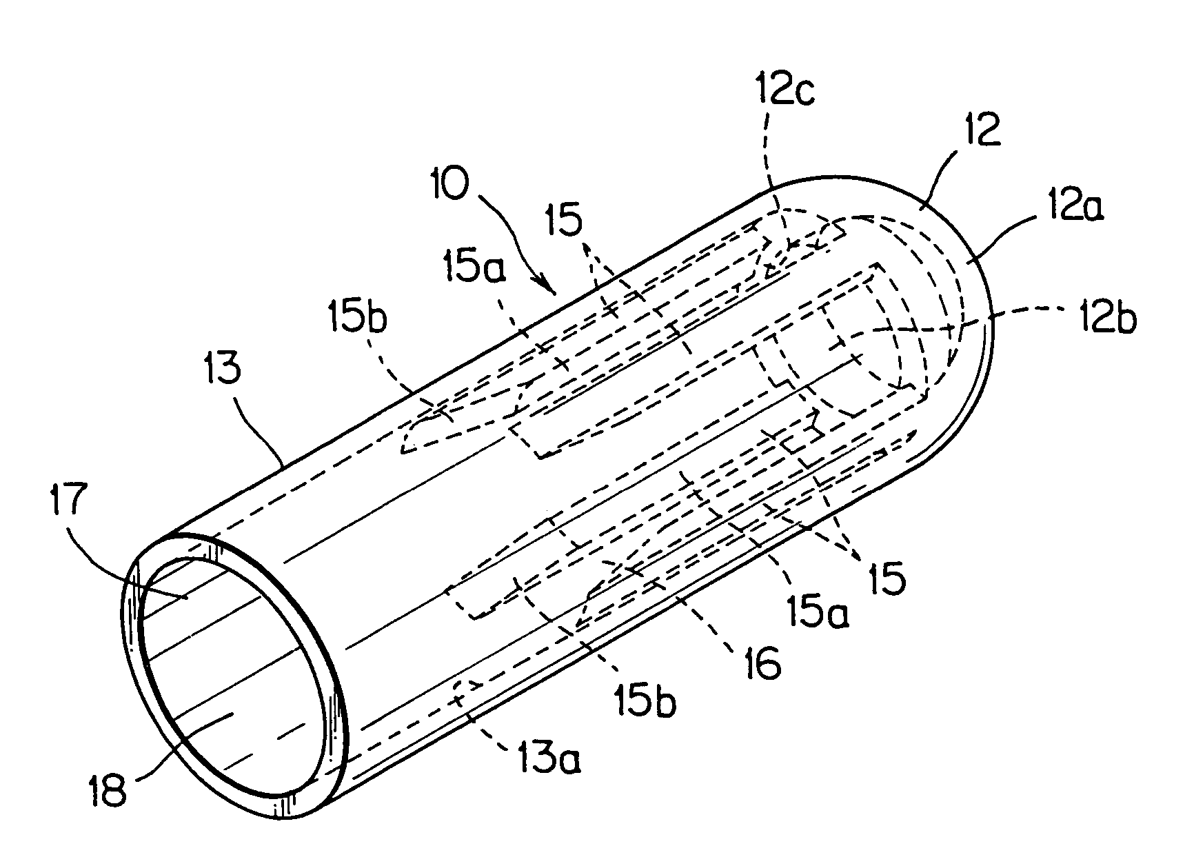
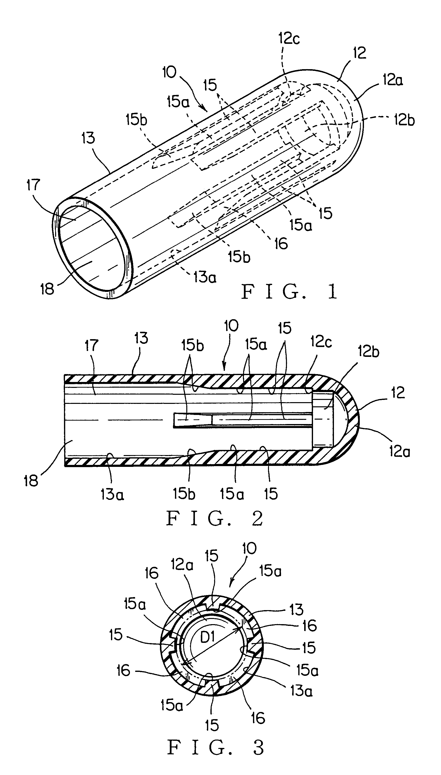
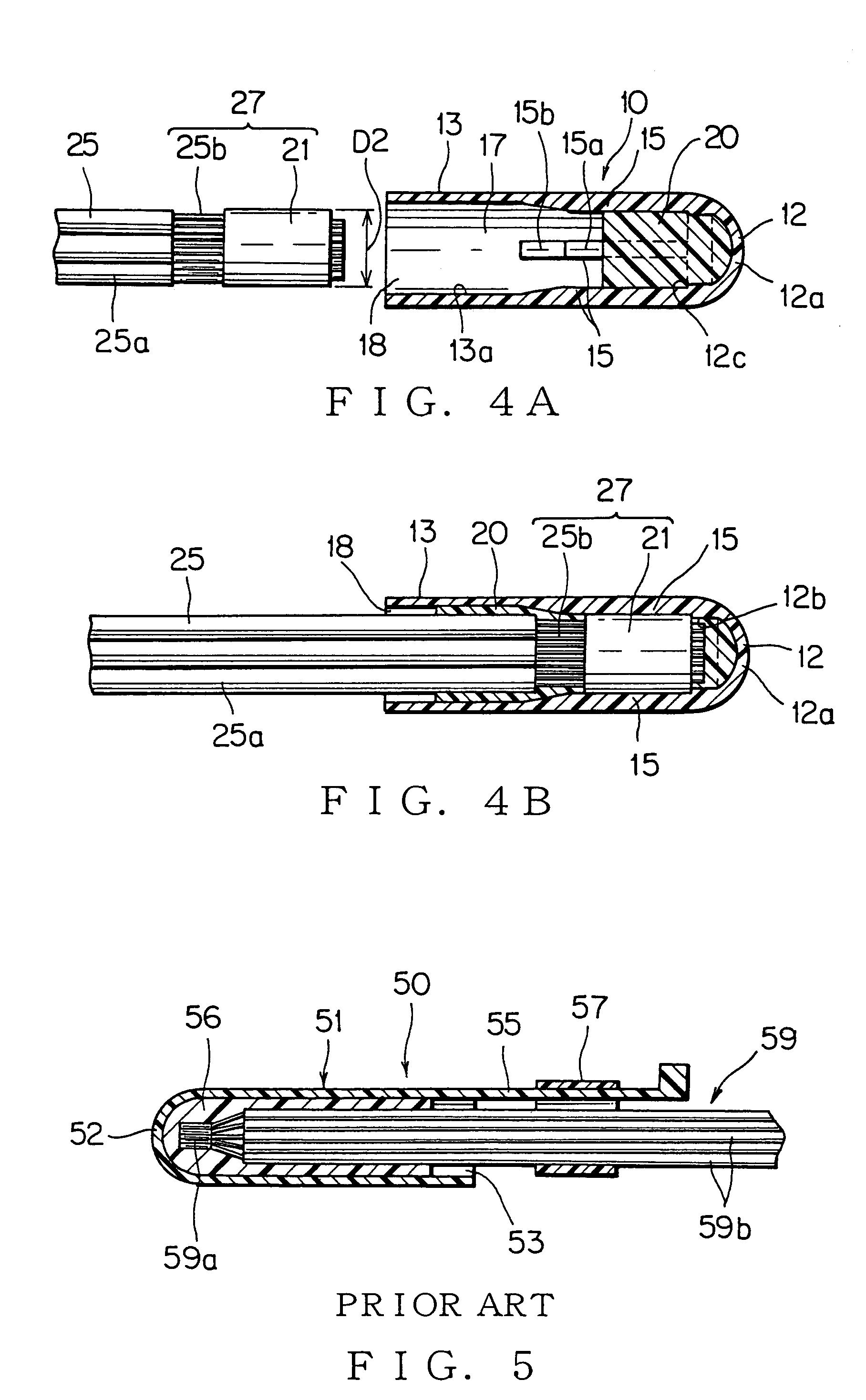
[0040]Referring to the accompanied drawings, an embodiment of the present invention will be discussed in detail hereinafter. FIGS. 1 to 4 show an embodiment of a connection cap and a cable connection method utilizing the connection cap according to the present invention.

[0041]A connection cap 10 is used for electrical connection of core wires of electrical cables 25 (sheathed cable) and for protecting a core portion 25b of the core wires in insulating and waterproof ability. For example, one of the electrical cables 25 is a lead from an electric circuit and the other is a cable connected to a battery. The electrical cable 25 may be a lead from a motor or an actuator like a solenoid. The electrical cable 25 also may be a branch line of a wiring harness or a lead from electric elements arranged in a junction box.

[0042]Each electrical cable 25 has an end stripped with respect to a sheath 25a to provide an exposed core portion 25b having a given length. The exposed length of the core po...


PUM


Abstract

A connection cap that includes a rear end wall positioned at a rear end of the connection cap for confining a sealing uncured resin, an opening positioned at a forward end of the connection cap for inserting a jointing portion of core wires of electrical cables, and a cylindrical wall extending from the opening to the rear end wall. The cylindrical wall has an inner surface formed with a plurality of ribs for positioning the jointing portion in the connection cap. The ribs are distributed in a circumferential direction to uniformly support the electrical cable. The uncured resin intrudes clearances each defined between adjacent two of the ribs. The inner surfaces of ribs define an inscribed circle having a diameter substantially the same as an outer diameter of a conductive sleeve for crimping the core wires. Advantageously, the ribs each have a forward end portion formed with a tapered surface gradually rising toward the rear end of connection cap.

Description

BACKGROUND OF THE INVENTION[0001]1. Field of the Invention[0002]The present invention relates to a connection cap and a cable connection method utilizing the same. The connection cap is used for connecting core wires of a plurality of sheathed cables to each other, so that the connection cap covers and holds a wire connection portion for insulation and waterproof protection of the connection portion.[0003]2. Background Art[0004]FIG. 5 shows a conventional one of such connection caps, for example disclosed in Japanese Patent Application Laid-open No. H. 10-243539.[0005]In FIG. 5, a connection cap 50 can easily cover core portions 59a of jointed cables 59 without a troublesome work for surrounding the core portions 59a with an insulative resin material. The connection cap 50 has a cap main body 51 that receives the core portions 59a. The resin material, which is in an uncured state, is injected into the cap main body 51 to cover the core portions 59a and sheathes 59b of the jointed ca...

Claims


Application Information

Patent Timeline
Patent Type & Authority Patents(United States)
IPC IPC(8): H01R13/52H01R4/22H01R4/70H02G15/04
CPCH01R4/70
Inventor SAKAGUCHI, TADAHISAONUMA, MASANORI
Owner YAZAKI CORP
Why Eureka
Try Eureka