
Zoom lens system and image pickup apparatus including the same

a technology of zoom lens and image pickup, which is applied in the field of zoom lens system, can solve the problems of reducing a size, reducing the size of the zoom lens, and insufficient compactness, so as to achieve desirable optical performance, reduce the number of lenses and the length of the entire lens, and achieve the effect of reducing the number of lenses

Inactive Publication Date: 2006-07-11
CANON KK
View PDF20 Cites 18 Cited by
  • Summary
  • Abstract
  • Description
  • Claims
  • Application Information

AI Technical Summary

Benefits of technology

[0019]The present invention has been made in view of the problems with respect to a zoom lens of a conventional type in which a lens unit having a negative refractive power precedes other lens units. An object of the present invention is to provide a zoom lens system capable of obtaining a desirable zoom ratio and desirable optical performance while having a structure in which reductions in the number of lenses and entire lens length are realized.

Problems solved by technology

H06-066008 includes a large number of lenses and is insufficient in view of compactness.
Though there is no problem when the zoom lens is used for silver-halide film camera, when the zoom lens is used for a digital still camera including a solid-state image pickup element, design power allocation is restricted, so a size of the zoom lens is likely to increase.
H07-052256 is inappropriate for a photographing optical system for digital still camera.
The zoom lens disclosed in U.S. Pat. No. 5,434,710 includes a large number of lenses, so there is a limitation to reduce a size thereof.
In addition, the lens arrangement is made to realize the super wide angle, so sufficient compactness is not obtained.
However, high performance suitable for a digital still camera having a high pixel density is not obtained.
Therefore, when an aspherical lens is used as the negative lens, there is a problem in that a manufacturing cost increases.

Method used


Image

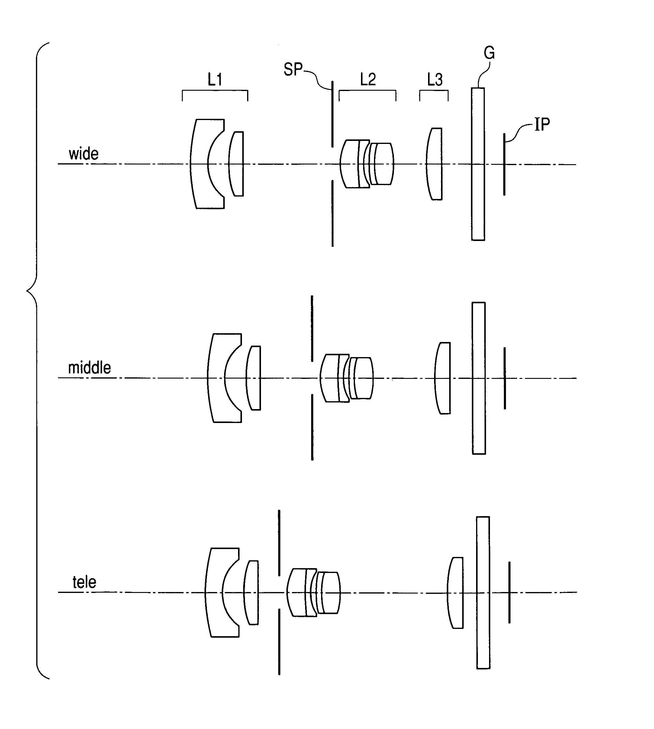
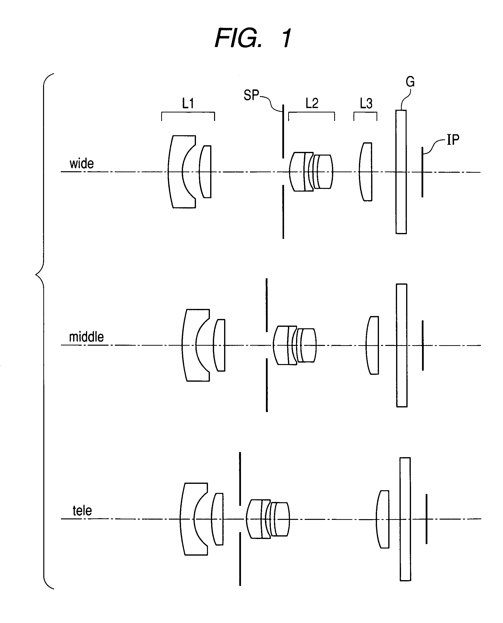
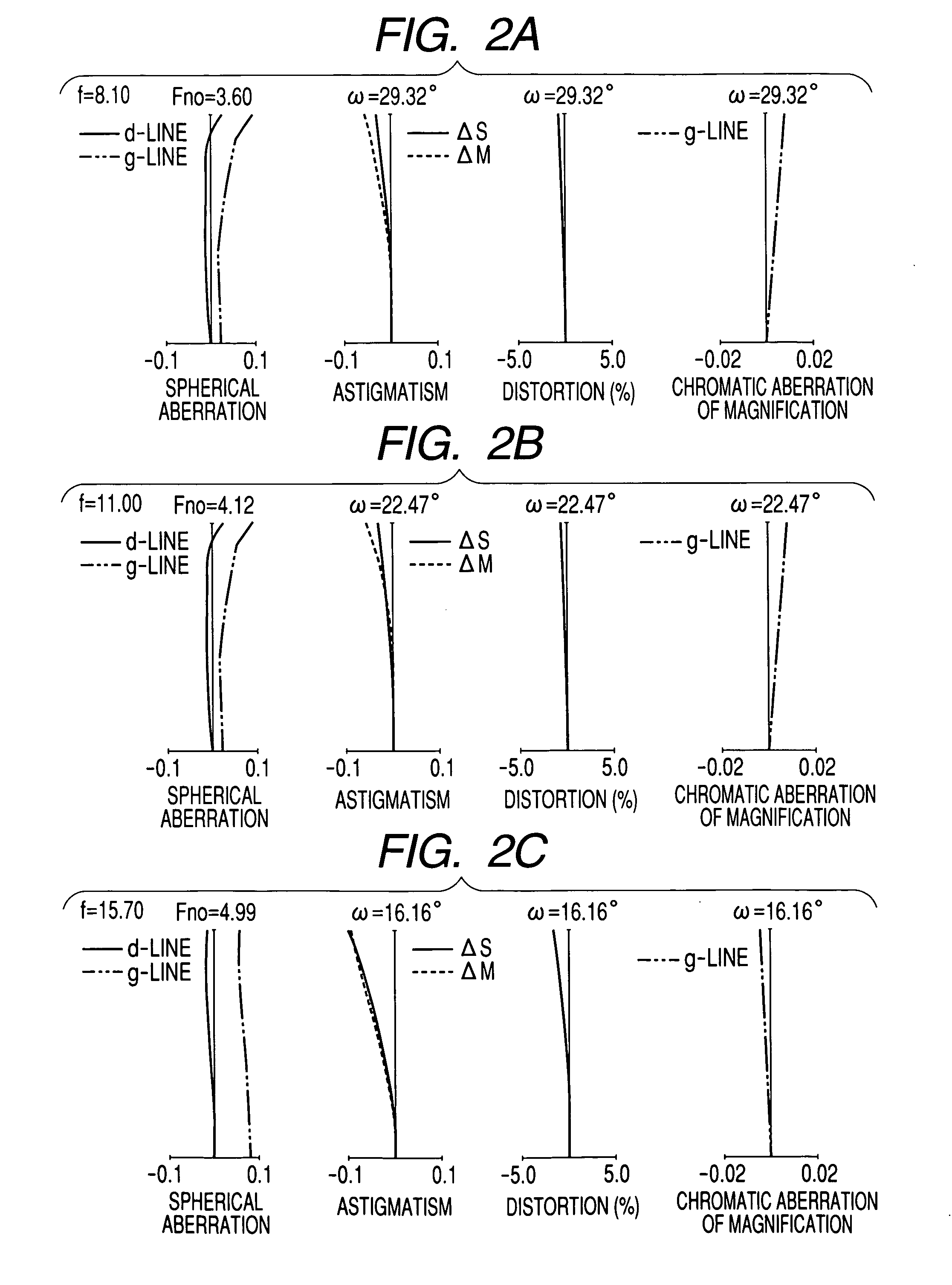
  • Zoom lens system and image pickup apparatus including the same
  • Zoom lens system and image pickup apparatus including the same
  • Zoom lens system and image pickup apparatus including the same

Examples


embodiment 1

NUMERAL EMBODIMENT 1

[0049]f=8.10˜15.70 Fno=3.60˜4.12 2ω=58.6˜32.3

[0050]

R1 = 31.177D1 = 2.50N1 = 1.772499ν1 = 49.6R2 = 6.249D2 = 3.03* R3 = 22.106D3 = 1.94N2 = 1.846660ν2 = 23.8R4 = 101.144D4 = VariableR5 = StopD5 = 1.03* R6 = 6.361D6 = 2.79N3 = 1.730770ν3 = 40.5R7 = 58.020D7 = 0.73N4 = 1.698947ν4 = 30.1R8 = 5.840D8 = 0.87R9 = 20.744D9 = 0.73N5 = 1.846660ν5 = 23.8R10 = 8.821D10 = 2.65N6 = 1.696797ν6 = 55.5R11 = −16.616D11 = VariableR12 = 20.287D12 = 2.21N7 = 1.517417ν7 = 52.4R13 = −2587.247D13 = VariableR14 = ∞D14 = 2.00N8 = 1.516330ν8 = 64.1R15 = ∞

[0051]

VariableFocal lengthinterval8.1011.0015.70D413.317.643.00D115.009.2515.98D134.283.582.20

Aspherical Coefficients

[0052]Third Surface

[0053]

k = 0.00000e+00A = 0B = 2.44934e−04C = −3.31138e−07D = 1.51612e−07E = −4.67258e−10

Sixth Surface

[0054]

k = −1.65377e+00A = 0B = 5.70807e−04C = 1.04001e−07D = 4.58874e−08E = 0.00000e+00

numerical embodiment 2

[0055]f=8.10˜15.70 Fno=2.84˜3.25 2ω=44.9˜24.1

[0056]

R1 = −778.924D1 = 2.50N1 = 1.638539ν1 = 55.4R2 = 6.918D2 = 3.57* R3 = 50.577D3 = 2.50N2 = 1.846660ν2 = 23.8R4 = −74.470D4 = VariableR5 = StopD5 = 1.03* R6 = 6.361D6 = 2.79N3 = 1.730770ν3 = 40.5R7 = 58.020D7 = 0.73N4 = 1.698947ν4 = 30.1R8 = 5.840D8 = 0.87R9 = 20.744D9 = 0.73N5 = 1.846660ν5 = 23.8R10 = 8.821D10 = 2.65N6 = 1.696797ν6 = 55.5R11 = −16.616D11 = Variable* R12 = 20.287D12 = 2.21N7 = 1.589129ν7 = 61.3R13 = −2587.247D13 = VariableR14 = ∞D14 = 2.00N8 = 1.516330ν8 = 64.1R15 = ∞

[0057]

VariableFocal lengthinterval8.1011.0015.70D411.585.640.65D117.1511.3117.45D133.472.591.20

Aspherical Coefficients

Third Surface

[0058]

K = 0.00000e+00A = 0B = 1.75060e−04C = 2.03087e−06D = −3.81094−08E = 1.65002e−09

Sixth Surface

[0059]

K = −1.65377e+00A = 0B = 5.70807e−04C = 1.04001e−07D = 4.58874e−08E = 0.00000e+00

[0060]

K = 0.00000e+00A = 0B = −2.43560e−05C = −2.26966e−08D = 4.72288e−09E = −3.66244e−11

numerical embodiment 3

[0061]f=8.10˜15.70 Fno=2.82˜3.31 2ω=58.6˜32.3

[0062]

R1 = 28.426D1 = 2.50N1 = 1.712995ν1 = 53.9R2 = 5.374D2 = 2.97* R3 = 25.820D3 = 1.70N2 = 1.846660ν2 = 23.8R4 = 337.253D4 = VariableR5 = StopD5 = 1.30* R6 = 6.361D6 = 2.79N3 = 1.730770ν3 = 40.5R7 = 58.020D7 = 0.73N4 = 1.698947ν4 = 30.1R8 = 5.840D8 = 0.87R9 = 20.744D9 = 0.73N5 = 1.846660ν5 = 23.8R10 = 8.821D10 = 2.65N6 = 1.696797ν6 = 55.5R11 = −16.616D11 = VariableR12 = 20.287D12 = 2.21N7 = 1.644757ν7 = 57.8R13 = −2587.247D13 = VariableR14 = ∞D14 = 2.00N8 = 1.516330ν7 = 64.1R15 = ∞

[0063]

VariableFocal lengthinterval8.1011.0015.70D411.246.863.00D116.0611.3618.68D134.233.292.20

Aspherical Coefficients

Third Surface

[0064]

k = 0.00000e+00A = 0B = 3.52168e−04C = 2.27503e−06D = 1.69721e−07E = 4.03257e−09

Sixth Surface

[0065]

k = −1.65377e+00A = 0B = 5.70807e−04C = 1.04001e−07D = 4.58874e−08E = 0.00000e+00

[0066]

TABLE 1ConditionalConditionalConditionalexpression (1)expression (2)expression (3)Embodiment 10.28−1.560.41Embodiment 20.14−0.190.42Embodime...


PUM


Abstract

A zoom lens system in which reductions in the number of lenses and entire lens length are realized is provided. The zoom lens system includes, in order from an object side to an image side, a first lens unit having negative optical power, a second lens unit having positive optical power, and a third lens unit having positive optical power. During zooming from a wide-angle end to a telephoto end, an interval between the first lens unit and the second lens unit reduces and an interval between the second lens unit and the third lens unit changes. An aspherical lens is used for a positive lens element of the first lens unit. Shapes of respective lens elements composing the first lens unit, an interval therebetween, and the like are suitably set.

Description

BACKGROUND OF THE INVENTION[0001]1. Field of the Invention[0002]The present invention relates to a zoom lens system, and more particularly to a zoom lens system suitable for use in a photographing optical system for a digital still camera using a solid image pickup element such as a CCD.[0003]2. Related Background Art[0004]In recent years, attention has been given to a so-called digital still camera for photographing a still image using a solid-state image pickup element such as a CCD. In order to reduce an entire size of the camera, an optical system having an extremely short entire lens length has been required for a zoom lens serving as a photographing optical system of the digital still camera.[0005]In view of a characteristic of the still image, it is desirable that the digital still camera have a wide field angle. Also, the digital still camera is required to have higher optical performance than that of a video camera for moving picture photographing.[0006]According to, for ex...

Claims


Application Information

Patent Timeline
Patent Type & Authority Patents(United States)
IPC IPC(8): G02B15/14G02B15/177
CPCG02B15/177G02B15/143507
Inventor ITOH, YOSHINORI
Owner CANON KK
Learn More