
Pool skimmer

Inactive Publication Date: 2006-07-18
STETABON MICHAEL A
View PDF21 Cites 24 Cited by
  • Summary
  • Abstract
  • Description
  • Claims
  • Application Information

AI Technical Summary

Benefits of technology

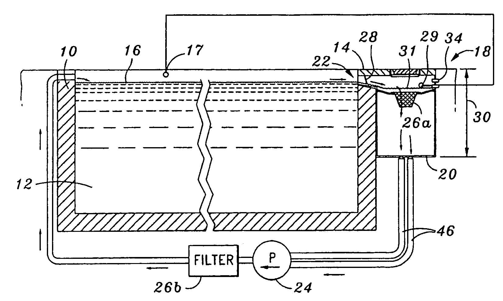
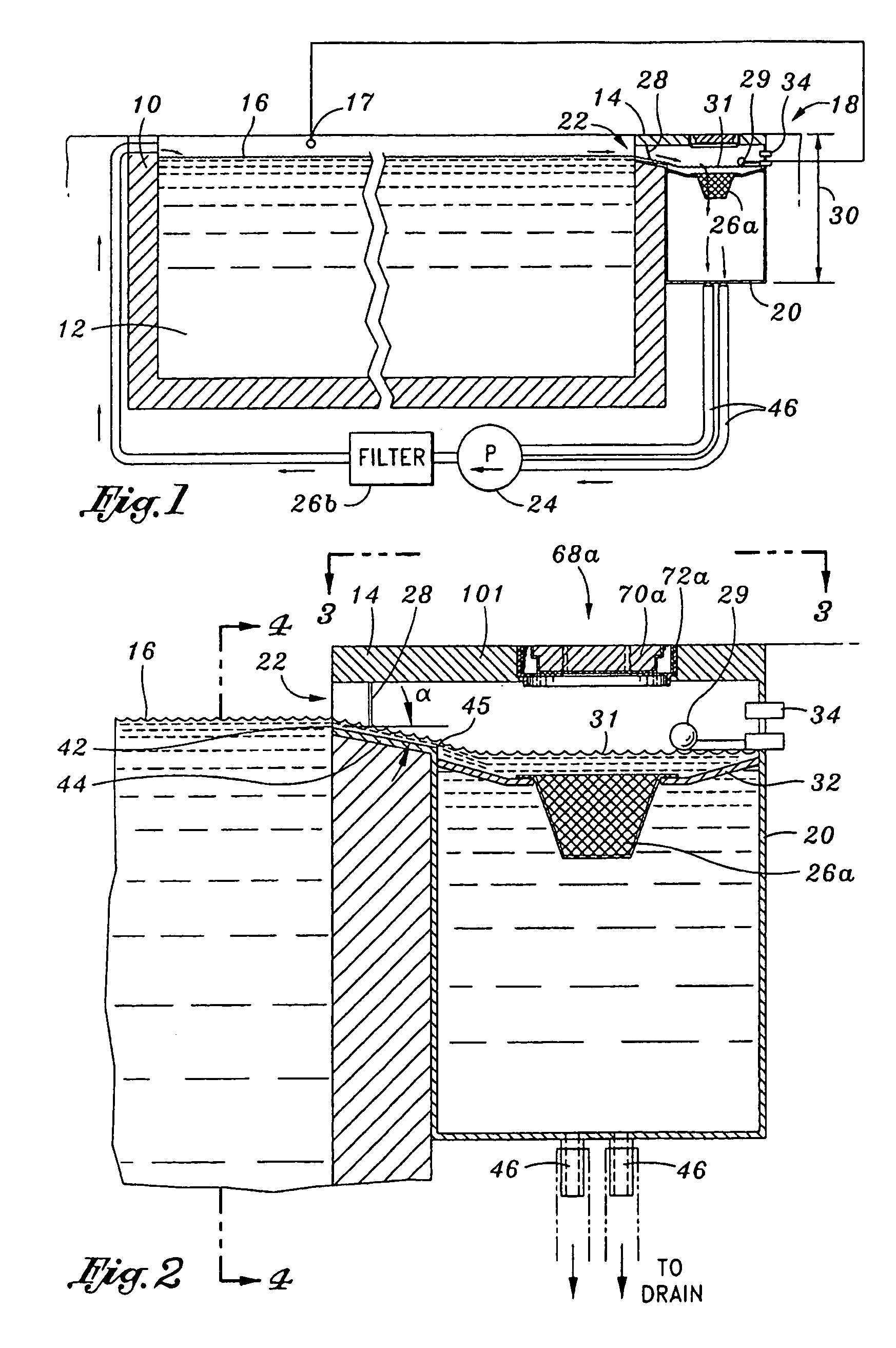
"The present invention provides a skimming system for a tank that can remove debris and keep the tank clean. The system includes a reservoir, an inlet, a filter, a reservoir pump, and a weir. The invention solves the problem of debris clogging the tank pump and allows for the continuous removal of debris from the tank. The skimming system is designed to maintain the level of the tank fluid surface below the level of the reservoir, preventing the pump from drawing air and ensuring a steady state condition. The system also includes a fluid level regulator to replenish the tank and reservoir with fluid as it evaporates. The invention improves the efficiency of the skimming system and ensures a clean tank."

Problems solved by technology

Unfortunately, debris is drawn toward but does not pass through the inlet.

Method used


Image

  • Pool skimmer
  • Pool skimmer
  • Pool skimmer

Examples


first embodiment

[0073]Referring now to FIGS. 5–7, the cap member 70a may also be provided with hollow finger grip tubes 92a having holes 96a extending through the material 82 to a flared bottom cavity 94a (see FIG. 7). The tubes 92a, and more particularly, the flared bottom cavity 94a may have a grip surface 98a (see FIG. 7) to provide a finger hold for lifting the cap member 70a and material 82 from the access opening.

second embodiment

[0074]Referring now to FIGS. 8–10, the cap member 70b and frame 72b may be provided which collectively form hollow finger grip tubes 92b (see FIG. 10) having holes 96b (see FIG. 10) extending through the material 82 to a flared bottom cavity 94b. The tubes 92b, and more particularly, the flared bottom cavity 94b may have a grip surface 98b (see FIG. 10) to provide a finger hold for lifting the cap member 70b and material 82 from the access opening.

[0075]The holes 96b as well as the flared bottom cavity 94b are defined by both the cap member 70b and the frame 72b. More particularly, the hole 96b may be defined by the lateral wall 90b of the cap member 70b and the side support 104b (see FIG. 8) of the frame 72b. As shown in FIG. 9, the lateral wall 90b may have at least one recess 106. The recess 106 when viewed from the top may have a semi circular configuration. The recess defines the inner periphery of the hole 96b. The outer periphery of the hole 96b may be defined by the side sup...

third embodiment

[0077]Referring now to FIGS. 11–13, the cap member 70c and frame 72c may be provided which also collectively form hollow finger grip tubes 92c (see FIG. 13) having holes 96c (see FIG. 13) extending through the material 82 to a flared bottom cavity 94c. The tubes 92c, and more particularly, the flared bottom cavity 94c may have a grip surface 98c (see FIG. 10) to provide a finger hold for lifting the cap member 70c and material 82 from the access opening.

[0078]The holes 96c as well as the flared bottom cavity 94c may be collectively defined by both the cap member 70c and the frame 72c. More particularly, the hole 96c may be defined by the lateral wall 90c of the cap member 70c and the side support 104c (see FIG. 11) of the frame 72c. As shown in FIG. 12, the side support 104c of the frame 72c may have at least one recess 108. The recess 108 when viewed from the top may have a semi circular configuration. The recess defines the outer periphery of the hole 96c. The inner periphery of t...


PUM

PropertyMeasurementUnit
angle of declinationaaaaaaaaaa
heightaaaaaaaaaa
decline angleaaaaaaaaaa

Abstract

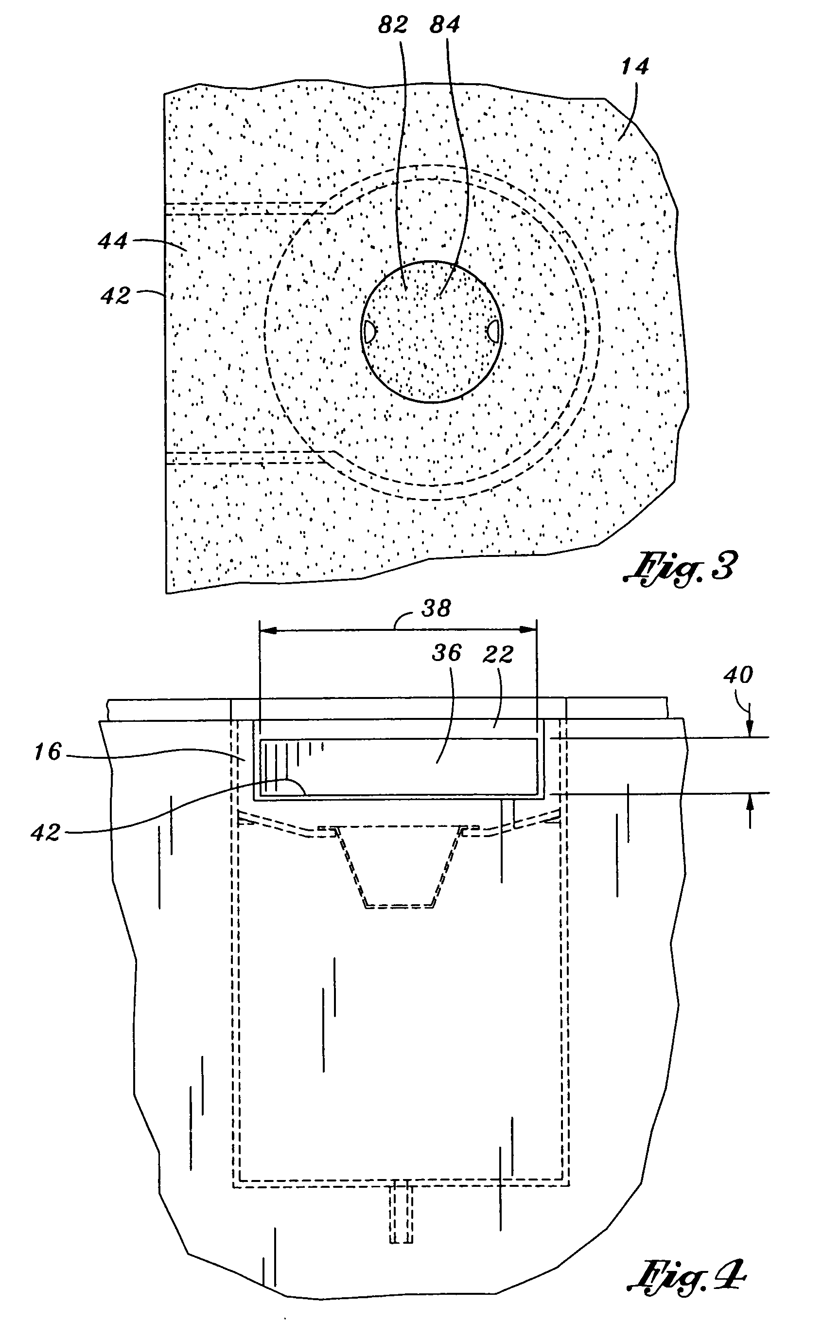
A skimmer system is provided which includes a reservoir, an inlet, a reservoir pump and a weir. The skimmer system may be attached to a tank having fluid therein. The fluid in the tank defines a tank fluid surface, and the fluid in the reservoir defines a reservoir fluid surface. The reservoir receives fluid from the tank via the inlet, and the tank receives fluid from the reservoir via the reservoir pump. When the skimmer system is activated, the level of the reservoir fluid surface may be maintained below the level of the tank fluid surface. The inlet edge is located below the level of the tank fluid surface. The inlet surface may decline away from the tank to direct the fluid from the tank to the reservoir. The filter is positioned between the inlet and the reservoir to retain particulate within the fluid. The weir defines a weir edge. The weir edge may be parallel to and substantially below the level of the tank fluid surface to allow particulate in the fluid to pass under the weir when the reservoir pump is activated and to prevent particulate in the fluid from passing under the weir when the reservoir pump is deactivated. The filter may be serviced through an access opening formed in a fabricated surface above the filter and covered by a cover.

Description

CROSS-REFERENCE TO RELATED APPLICATIONS[0001]This is a continuation-in-part of application Ser. No. 10 / 612,745, filed Jul. 2, 2003, the entire contents of which are expressly incorporated herein by reference.STATEMENT RE: FEDERALLY SPONSORED RESEARCH / DEVELOPMENT[0002]Not ApplicableBACKGROUND OF THE INVENTION[0003]The present invention relates generally to circulation systems which cause fluid to flow through various system components for the purposes of clarifying, heating, purifying and returning the fluid back to the original body of fluid, and more particularly, to a pool skimmer system which cause water to flow through a basket to remove debris floating on the surface of a pool and to return the water back to the pool.[0004]In the context of swimming pools, the water in the pool is filtered through a circulation system to filter debris from the water. In particular, the circulation system has a reservoir attached adjacent to the pool. The reservoir and the pool are attached to e...

Claims


Application Information

Patent Timeline
Patent Type & Authority Patents(United States)
IPC IPC(8): E04H4/00E04H4/12
CPCE04H4/1272
Inventor STETSON, MICHAEL A.
Owner STETABON MICHAEL A
Learn More