Image reading and recording apparatus

a reading and recording technology, applied in the field of image reading and recording equipment, can solve the problems of limiting the realization of miniaturization and low cost of facsimile, and achieve the effect of reducing cost and high quality read imag

Inactive Publication Date: 2006-07-18
CANON KK
View PDF17 Cites 29 Cited by
  • Summary
  • Abstract
  • Description
  • Claims
  • Application Information

AI Technical Summary

Benefits of technology

[0009]Accordingly, an object of the present invention is to provide an image reading and recording apparatus capable of realizing the miniaturization and a low cost of the apparatus main body, and executing highly sophisticated image reading and high quality image recording.
[0011]According to the image reading and recording apparatus of the present invention, the document can be read certainly, and a high quality read image can be obtained by preventing introduction of an external light beam at the time of pre-scanning (white reference adjustment) before a reading operation. Furthermore, an image recording operation to the recording sheet, and an image reading operation of the document can be executed by a common driving source.
[0012]In particular, according to the image reading and recording apparatus of the present invention, since selective feed of a recording sheet and a document, and operation of moving the means can be executed by one driving source, the miniaturization of the apparatus itself and cost reduction can be realized.

Problems solved by technology

However, according to the facsimile 300, since independent feed mechanisms have been required for feeding the document D and the recording paper P, there has been a limitation for realizing the miniaturization and a low cost of the facsimile 300.

Method used


Image

  • Image reading and recording apparatus
  • Image reading and recording apparatus
  • Image reading and recording apparatus

Examples


Embodiment Construction

[0081]Hereinafter, embodiments of the present invention will be explained with reference to the drawings.

[0082]The size, the material, the shape, the relative arrangement thereof, or the like of the constituent parts disclosed in the embodiments do not limit the scope of the present invention thereto unless otherwise specified.

[0083]Moreover, in the explanation below, the terminology “contact image sensor” is abbreviated as the “CS”.

Entire Configuration of the Image Reading and Recording Apparatus

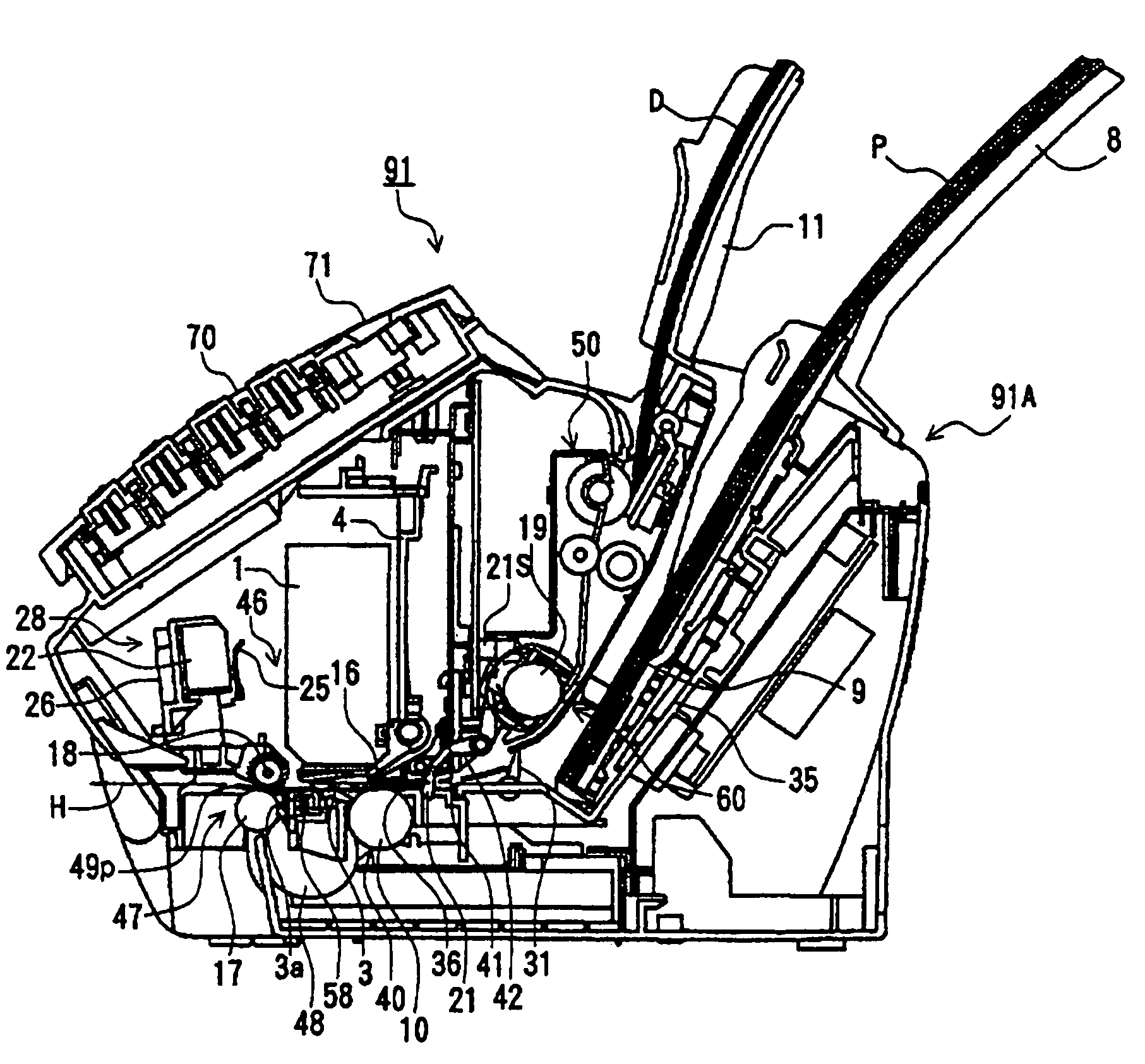
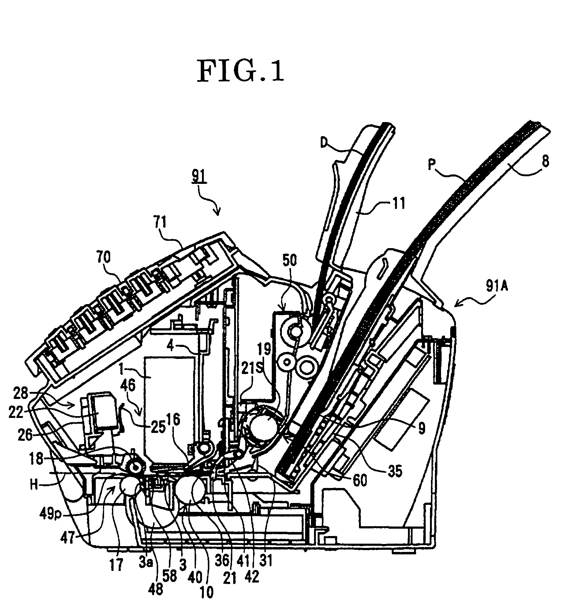
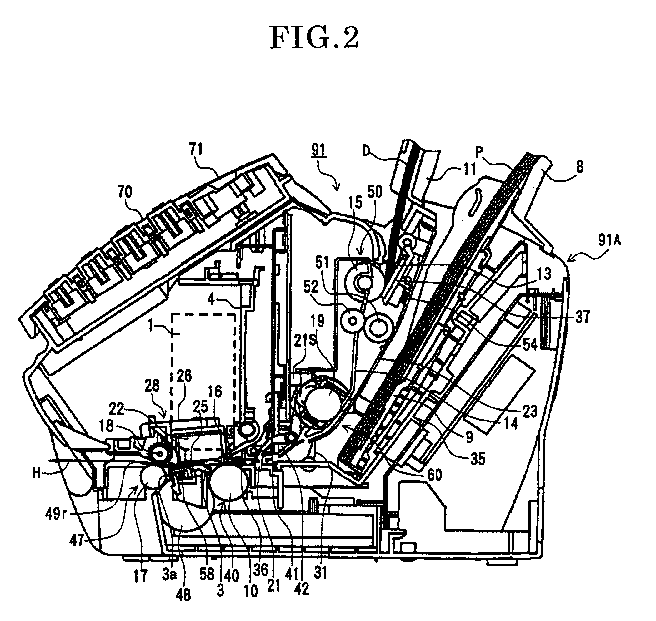
[0084]FIG. 1 is a cross-sectional view taken along the feeding direction of the document D and the recording paper P in the image reading and recording apparatus 91 of an embodiment of the present invention, showing the state of recording an image on the recording paper P. FIG. 2 is a diagram showing the state of reading the document D in the image reading and recording apparatus 91 of FIG. 1. FIG. 3 is a cross-sectional view taken along the feeding direction of the document D and the recor...


PUM


Abstract

The present invention relates to an image reading and recording apparatus comprising: a driving source; a recording sheet feeding means for feeding a recording sheet; recording means for recording an image in a predetermined recording area on the recording sheet, supplied by the recording sheet feeding means, and movable to outside of the recording area; document feeding means for feeding a document; reading means movable between the reading position for reading an image on the document, fed by the document feeding means, and the stand by position withdrawn from the reading position; a document feeding force transmitting means for transmitting the driving force of the driving source to the document feeding means; and moving means for moving the reading means to the reading position by the driving force of the driving source at the time the recording means is moved to the outside of the recording area.

Description

BACKGROUND OF THE INVENTION[0001]1. Field of the Invention[0002]The present invention relates to an image reading and recording apparatus comprising integrally reading means for reading an image of a document, and recording means for recording (printing) an image on a recording medium, such as a facsimile.[0003]2. Description of the Related Art[0004]With reference to FIG. 68, an ink jet recording type facsimile, which has conventionally been used frequently, will be explained as an example of an image reading and recording apparatus.[0005]Recording papers P are placed on a recording paper supporting member 303 so as to be supplied one by one into an apparatus main body 300A of a facsimile 300 by a recording paper feeding roller 304 and an unshown separating mechanism. The recording paper P supplied into the apparatus main body 300A is fed to a printing part 306 by a feeding roller 305 so that an image is formed on the upper surface thereof by an image forming mechanism such as an in...

Claims


Application Information

Patent Timeline
Patent Type & Authority Patents(United States)
IPC IPC(8): B41J11/00H04N1/00B41J2/175B41J29/02B41J29/38H04N1/04
CPCB41J2/1752B41J29/38B41J29/02
Inventor AWAI, TAKASHIOKUBO, AKIOTERASHIMA, HIDEYUKISUZUKI, YOSHIAKI
Owner CANON KK
Why Eureka
Try Eureka