Securing device for electrical connectors and application thereof

a technology of electrical connectors and securing devices, which is applied in the direction of coupling device details, coupling device connections, coupling parts engagement/disengagement, etc., can solve the problems of no possibility to exploit a common power supply unit, additional costs and no possibility to exploit the existing psu, and mounting arrangements involve tedious operations by end users. , to achieve the effect of convenient installation

Active Publication Date: 2006-07-18
INTERDIGITAL MADISON PATENT HLDG
View PDF7 Cites 14 Cited by
  • Summary
  • Abstract
  • Description
  • Claims
  • Application Information

AI Technical Summary

Benefits of technology

[0014]Thus, an intermediary device is used for securing the two connectors. The intermediary device is able to receive the first connector in its hollow and to be secured to the panel by means of the clips for providing the link to the second connector. The laterally decreasing size of the outward opening offers a very convenient way to fix the first connector while enabling it to receive several possible models and sizes of the first connector.
[0015]A significant advantage of this solution is that the first electrical connector is held safely in the securing device. Further, this can be true for various models of this first electrical connector, having different sizes and forms. Also, the securing device is user-friendly and convenient to install for end users.
[0017]Preferably, the outward opening extends along the hollow from the front end towards the rear end of the securing device. This can make operations easier for the user. The term “towards the rear end”, means that the rear end of the securing device is not necessarily reached by the hollow.
[0021]In still another embodiment, the securing device contains a flexible material inside, forming the limits of the hollow, so flexible as to allow expansion of the outward opening under internal pressure. This enables one to force the first connector into the hollow, while the connector is maintained therein by pressure thereon, and to take it off by forcing it out of the hollow. Preferably, the securing device is flexible making it easier to move the clips closer together.

Problems solved by technology

This arrangement requires special installations and mounting elements, resulting in additional costs and no possibility to exploit a common power-supply unit (hereinafter referred to as “PSU”).
Such a mounting arrangement involves tedious operations by the end users.
However, this would involve special manufacturing, and thus additional costs and no possibility to exploit the existing PSU.
However, such an arrangement may experience frequent failures, due to movements of the connector plug through the back-panel.

Method used


Image

  • Securing device for electrical connectors and application thereof
  • Securing device for electrical connectors and application thereof
  • Securing device for electrical connectors and application thereof

Examples


Embodiment Construction

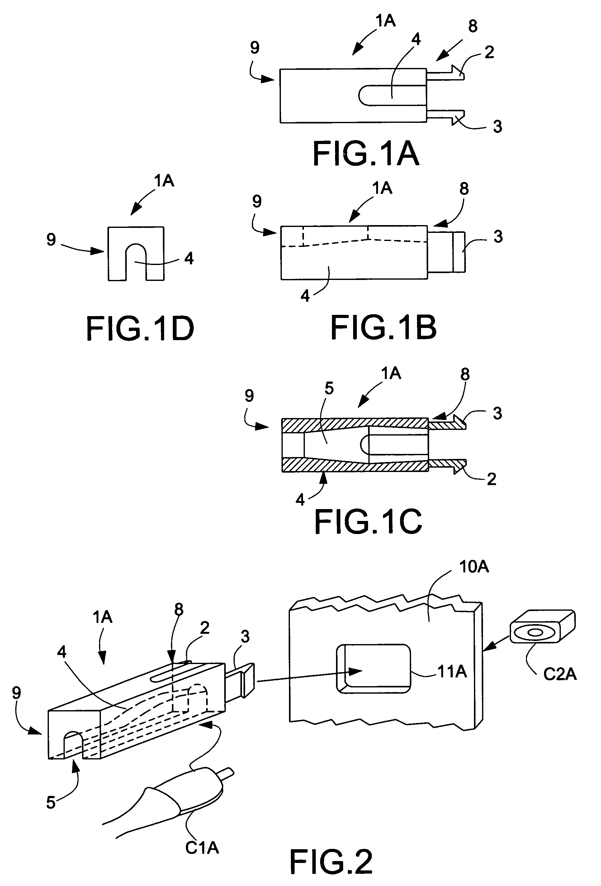
[0040]In the Figures, the references of the first and second embodiment may be completed with suffixes “A”, “B” and “C” corresponding respectively to the first, second and third embodiments. The notation without those suffixes then relates to a generic designation of the concerned objects. Also, corresponding parts of the securing device in both embodiments may be noted with the same references.

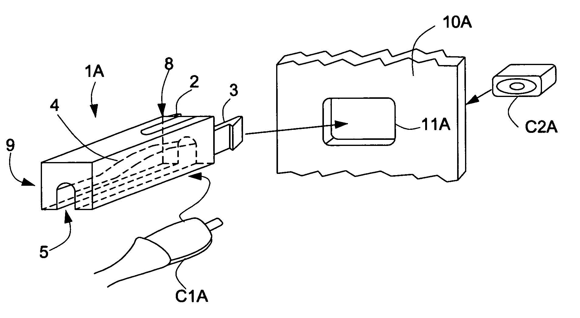
[0041]A securing device 1 according to a first embodiment, noted 1A, (FIGS. 1A to 1D and 2) is intended to maintain a PSU connector C1 with an electrical connector C2 internal to an electrical apparatus (such as for example a DSL modem) having a back-panel 10 (notation 10A in that embodiment). The PSU connector C1, noted C1A, has a contact pin and the internal connector C2, noted C2A, is intended to receive that pin and to have it maintained inside. The two connectors C1A and C2A may be linked through a window 11 of the panel 10A, noted 11A in that embodiment and having a rectangular shape.

[0...


PUM


Abstract

A securing device for maintaining a first electrical connector in contact with a second electrical connector through at least one window of a panel, the second connector being arranged behind that panel, is disclosed. The securing device includes at least two clips arranged on a front end to be directed towards the panel, at least one hollow starting from the front end and extending towards a rear end of the securing device, and at least one outward opening leading into it.

Description

BACKGROUND OF THE INVENTION[0001]1. Field of the Invention[0002]The present invention relates to a securing device for maintaining in contact electrical connectors, one of them being arranged behind a panel. It also relates to the connection of a power-supply unit and of an electrical apparatus.[0003]For connecting an electrical apparatus such as a DSL modem (for “Digital Subscriber Line”) to a power-supply, it is increasingly required that a power-supply cord be securely connected so as to avoid accidental disconnects.[0004]2. Description of the Prior Art[0005]The document U.S. Pat. No. 4,812,133 discloses a floating mount for an electrical connector assembly, which has a retaining clip snapped over a receptacle for securing on a panel. More precisely, a floating first electrical connector (receptacle) has contacts adapted to mate with complementary contacts carried by a: second electrical connector (plug) and has a limited floating movement within the plane of an opening in the pa...

Claims


Application Information

Patent Timeline
Patent Type & Authority Patents(United States)
IPC IPC(8): H01R13/60H01R9/03H01R13/46H01R13/639H01R13/627H01R13/629H01R13/73H01R13/74
CPCH01R13/745H01R13/6273H01R13/6395E04F21/08E04G21/04
Inventor MATTHYS, GEERTVAN DEN BOSSCHE, GEERTWITHOFS, TIM
Owner INTERDIGITAL MADISON PATENT HLDG
Why Eureka
Try Eureka