Developing cartridge detachable from image forming device

a development cartridge and image forming technology, applied in the field of developing cartridges, can solve the problems of affecting the repair of defective electrodes, the electrodes are contact with the end of the roller shaft, and the development bias is not properly applied to the developing roller, so as to achieve the effect of easy remediation

Inactive Publication Date: 2006-07-18
BROTHER KOGYO KK
View PDF23 Cites 60 Cited by
  • Summary
  • Abstract
  • Description
  • Claims
  • Application Information

AI Technical Summary

Benefits of technology

[0011]It is an objective of the present invention to provide a removable member and an image forming device wherein problems with electrodes or other members for establishing an electrical connection between the removable member and the image forming device can be easily remedied.

Problems solved by technology

When an electrode deforms excessively, contact between the electrode and the end of the roller shaft can become defective so that the developing bias is not properly applied to the developing roller.
However, the user cannot easily repair such a defective electrode because the electrodes are disposed within the casing of the laser printer.
This can be a troublesome experience.
The same problem can be found in a variety of different removable members that are used in laser printers or other image forming devices.

Method used


Image

  • Developing cartridge detachable from image forming device
  • Developing cartridge detachable from image forming device
  • Developing cartridge detachable from image forming device

Examples


Embodiment Construction

[0032]Next, a color laser printer 1 according to an embodiment of the present invention will be described with reference to FIGS. 1 to 6.

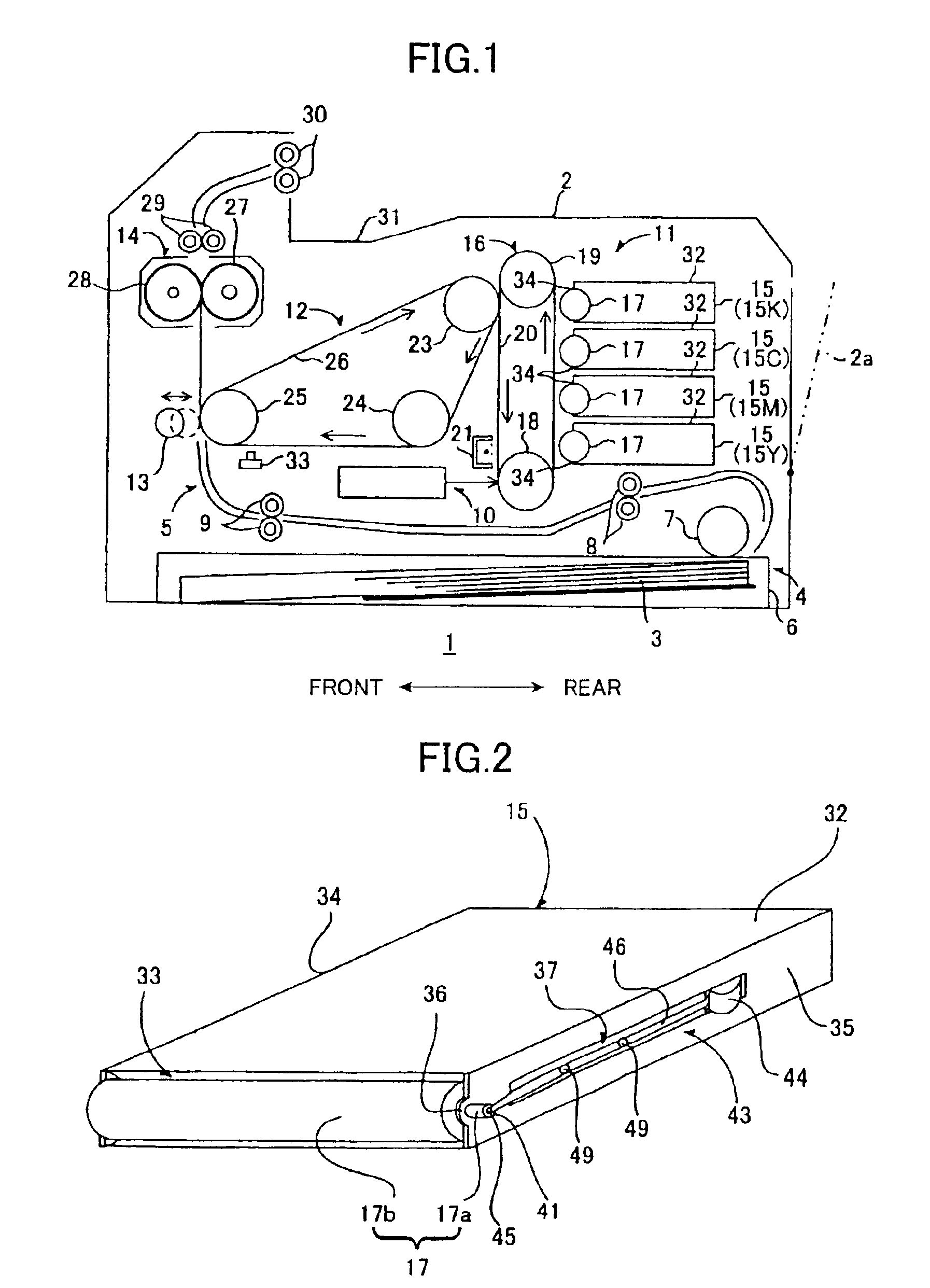
[0033]As shown in FIG. 1, the laser printer 1 includes a casing 2 and various components, such as a feeder 4 and an image forming unit 5, housed in the casing 2. The feeder 4 is for supplying sheets 3 to the image forming unit 5. The image forming unit 5 forms images on the supplied sheets 3. In the following explanation, the “front” of the color printer 1 will refer to the left side of FIG. 1 and the “rear” of the color printer 1 will refer to the right side of FIG. 1.

[0034]A rear cover 2a is provided pivotably about a hinge provided on the rear wall of the casing 2. The rear cover 2a can be freely pivoted open and closed about the hinge. The open position of the rear cover 2a is indicated in two-dot chain line in FIG. 1.

[0035]The feeder 4 includes a sheet-feed tray 6, a sheet-supply roller 7, transport rollers 8, and registration rollers 9. The s...


PUM


Abstract

A toner cartridge for use in a printer includes a developing roller and an electrode. The toner cartridge is mountable in the printer by moving in a mounting direction and removable from the printer by moving in a removal direction. The developer roller supplies toner to a photosensitive member of the printer. The electrode is for electrically connecting with a bias supply electrode of the printer to supply a bias to the developing roller. The electrode moves, in a direction from outside the housing toward the interior of the housing and orthogonal to the mounting direction and the removal direction, under contact with the printer while the developing cartridge is being mounted in the printer. The electrode is electrically connected with the bias supply electrode of the printer while the developing cartridge is mounted in the printer.

Description

BACKGROUND OF THE INVENTION[0001]1. Field of the Invention[0002]The present invention relates to a developing cartridge that is freely mountable in and removable from an image forming device.[0003]2. Description of Related Art[0004]Color laser printers are capable of forming images in full color. A color laser printer is provided with a plurality of different developing cartridges, each holding a different color of toner. The developing cartridges are freely mountable in and removable from the laser printer.[0005]Each developing cartridge includes a housing, a developing roller, a layer thickness regulating blade, and a supply roller. The housing is formed with a toner holding chamber that holds the toner in the color that corresponds to the developing cartridge. The developing roller, the layer thickness regulating blade, and the supply roller are housed in the housing. The toner contained in the toner holding chamber is supplied to the developing roller by the supply roller. The t...

Claims


Application Information

Patent Timeline
Patent Type & Authority Patents(United States)
IPC IPC(8): G03G15/00G03G15/01G03G15/08
CPCG03G15/0121G03G15/0875G03G15/80G03G2215/066
Inventor YOKOI, KATSUYUKI
Owner BROTHER KOGYO KK
Why Eureka
Try Eureka