Light-emitting floor tile burying structure and method adapting to concrete pavement deformation

A technology for concrete pavement and concrete slab, which is applied to semiconductor devices of light-emitting elements, roads, roads, etc., to achieve the effect of improving tensile strength, good integrity, and ensuring close contact

Inactive Publication Date: 2020-07-10
NANTONG UNIVERSITY
View PDF7 Cites 4 Cited by
  • Summary
  • Abstract
  • Description
  • Claims
  • Application Information

AI Technical Summary

Problems solved by technology

[0004] The purpose of the present invention is to provide a luminous floor tile embedding structure and method that adapt to the deformation of concrete pavement. In view of the problem of uneven subsidence and cracking of the road surface caused by the new type of intelligent traffic sign-luminous floor tile under the influence of vehicle load, a kind of enhanced The structural construction method of the pavement service performance at this place, to solve the problems raised in the above-mentioned background technology

Method used


Image

  • Light-emitting floor tile burying structure and method adapting to concrete pavement deformation
  • Light-emitting floor tile burying structure and method adapting to concrete pavement deformation
  • Light-emitting floor tile burying structure and method adapting to concrete pavement deformation

Examples


Embodiment Construction

[0033] The following will clearly and completely describe the technical solutions in the embodiments of the present invention with reference to the accompanying drawings in the embodiments of the present invention. Obviously, the described embodiments are only some, not all, embodiments of the present invention. Based on the embodiments of the present invention, all other embodiments obtained by persons of ordinary skill in the art without making creative efforts belong to the protection scope of the present invention.

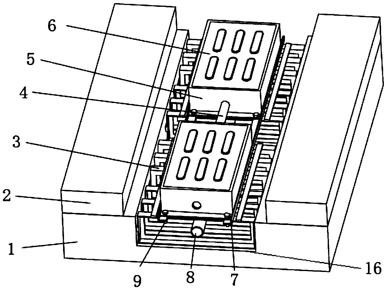
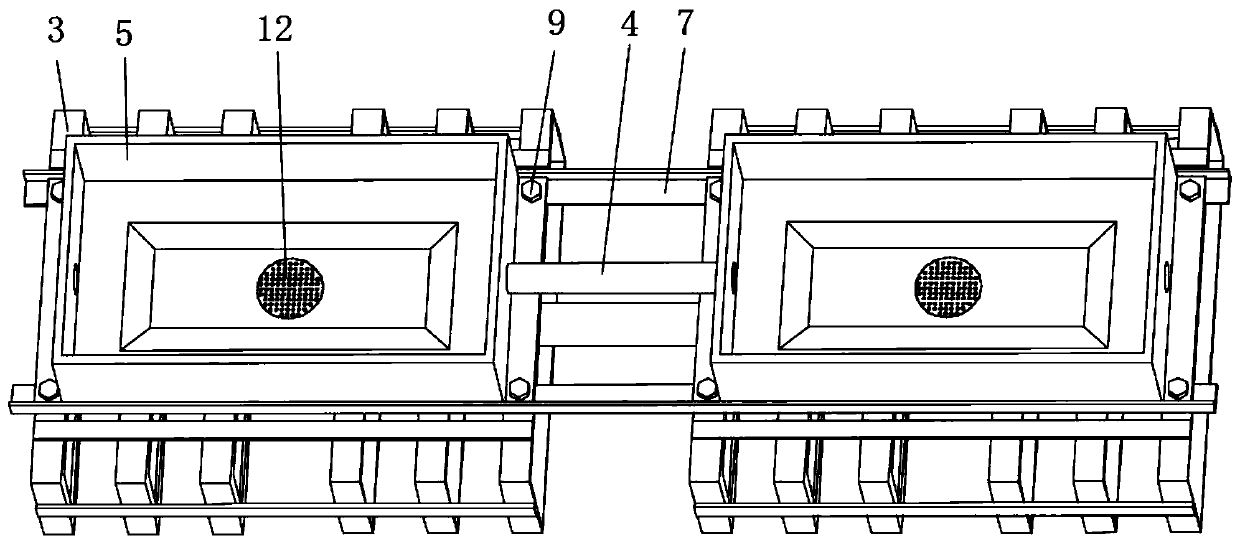
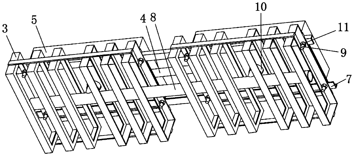
[0034] see Figure 1 to Figure 5 , the present invention provides a technical solution: a luminous floor tile embedding structure adapted to the deformation of concrete pavement, including a concrete slab 1, an asphalt overlay 2, a steel cage 3, a threading pipe 4, a box body 5, a light-transmitting resin block 6, Angle steel 7, drainage pipe 8, bolt 9, joint 10, hex nut 11, filter screen 12, sealing washer 13, support block 14, LED light-emitting board 15, gr...


PUM

PropertyMeasurementUnit
depthaaaaaaaaaa
widthaaaaaaaaaa
diameteraaaaaaaaaa

Abstract

The invention discloses a light-emitting floor tile burying structure and method adapting to concrete pavement deformation. A groove is embedded above a concrete slab; a reinforcement cage is arrangedin the groove; a supporting boss is arranged at the edge of the bottom of an inner cavity of each box body; a water collecting pit is formed in the center of the bottom of the box body; a circular hole is formed in the side wall of the box body; the bottom of the box body is arranged on the upper surface of the reinforcement cage through angle steel; two ends of each threading pipe are arranged between every two adjacent box bodies through the circular holes; one end of each joint is arranged in the middle below each box body; a filter screen is arranged above the middle lug part of each joint; a sealing washer is arranged below the middle lug portion of each joint, the other end of the joint is connected with a drainage pipe, an asphalt paving layer is arranged above the concrete slab, acable is arranged in each threading pipe, a supporting block is arranged above the supporting boss, an LED light-emitting plate is arranged above the supporting block, and a light-transmitting resinblock is arranged above the LED light-emitting plate. The pouring type reinforced concrete structure has the advantages of being good in integrity and large in rigidity, and the tensile strength of concrete is effectively improved.

Description

technical field [0001] The invention relates to the technical field of luminous floor tiles, in particular to a luminous floor tile embedding structure and method adapted to the deformation of concrete pavement. Background technique [0002] According to the data released by the Traffic Management Bureau, there have been 14,000 motor vehicle and pedestrian traffic accidents on zebra crossings across the country in the past three years, and the traffic accident rate in nighttime, rainy days, smog and other environments is five times that of usual above. The main reason that causes this phenomenon is: a pedestrian's disregard for the awareness of traffic regulations, the driver of the second motor vehicle is inattentive, and extreme weather will also hinder the driver's line of sight simultaneously. In response to such problems, a new type of intelligent traffic sign - luminous floor tiles (201920093826.5) emerged as the times require, which not only strengthens the safety aw...

Claims


Application Information

Patent Timeline
Patent Type & Authority Applications(China)
IPC IPC(8): E01C5/04E01C11/22E01F9/524F21S8/02F21V3/06F21V23/06F21V33/00F21Y115/10
CPCE01C5/04E01C11/225E01F9/524F21S8/022F21V23/06F21V33/00F21Y2115/10F21V3/0625
Inventor 徐勋倩施卫东杨威徐海黎沈标王建波项宏亮周井玲顾钰雯付尚静
Owner NANTONG UNIVERSITY
Why Eureka
Try Eureka