Postal sorting machine including a bin-transfer structure

a sorting machine and bin transfer technology, applied in the direction of conveyors, conveyor parts, instruments, etc., can solve the problems of increasing the time required for preparing delivery rounds, increasing the risk of bins being interchanged during temporary storage, and wasting a lot of time in preparing delivery rounds with such sorting machines, so as to reduce the risk of bins being interchanged, reduce the risk of reloading time, and reduce the effect of manual operation

Inactive Publication Date: 2006-07-25
SOLYSTIC
View PDF12 Cites 27 Cited by
  • Summary
  • Abstract
  • Description
  • Claims
  • Application Information

AI Technical Summary

Benefits of technology

[0006]The object of the present invention is to remedy the above drawbacks by proposing a postal sorting machine which minimizes manual operations, reduces reloading time, and reduces the risk of bins being interchanged between two sorting passes.

Problems solved by technology

That resulted in a risk of bins being interchanged during temporary storage on the carriage, having the effect of introducing malfunction into the preparation of delivery rounds.
In addition, such handling operations increase the time required for preparing delivery rounds.
As a result, preparing delivery rounds with such sorting machines takes a long time, requires a great detail of handling, and requires considerable attention to be paid by the operators.

Method used


Image

  • Postal sorting machine including a bin-transfer structure
  • Postal sorting machine including a bin-transfer structure
  • Postal sorting machine including a bin-transfer structure

Examples


Embodiment Construction

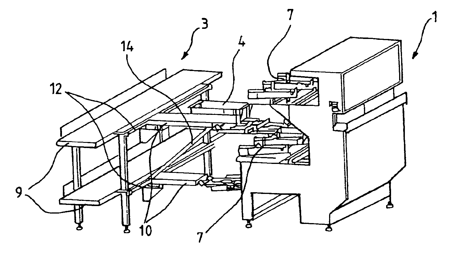
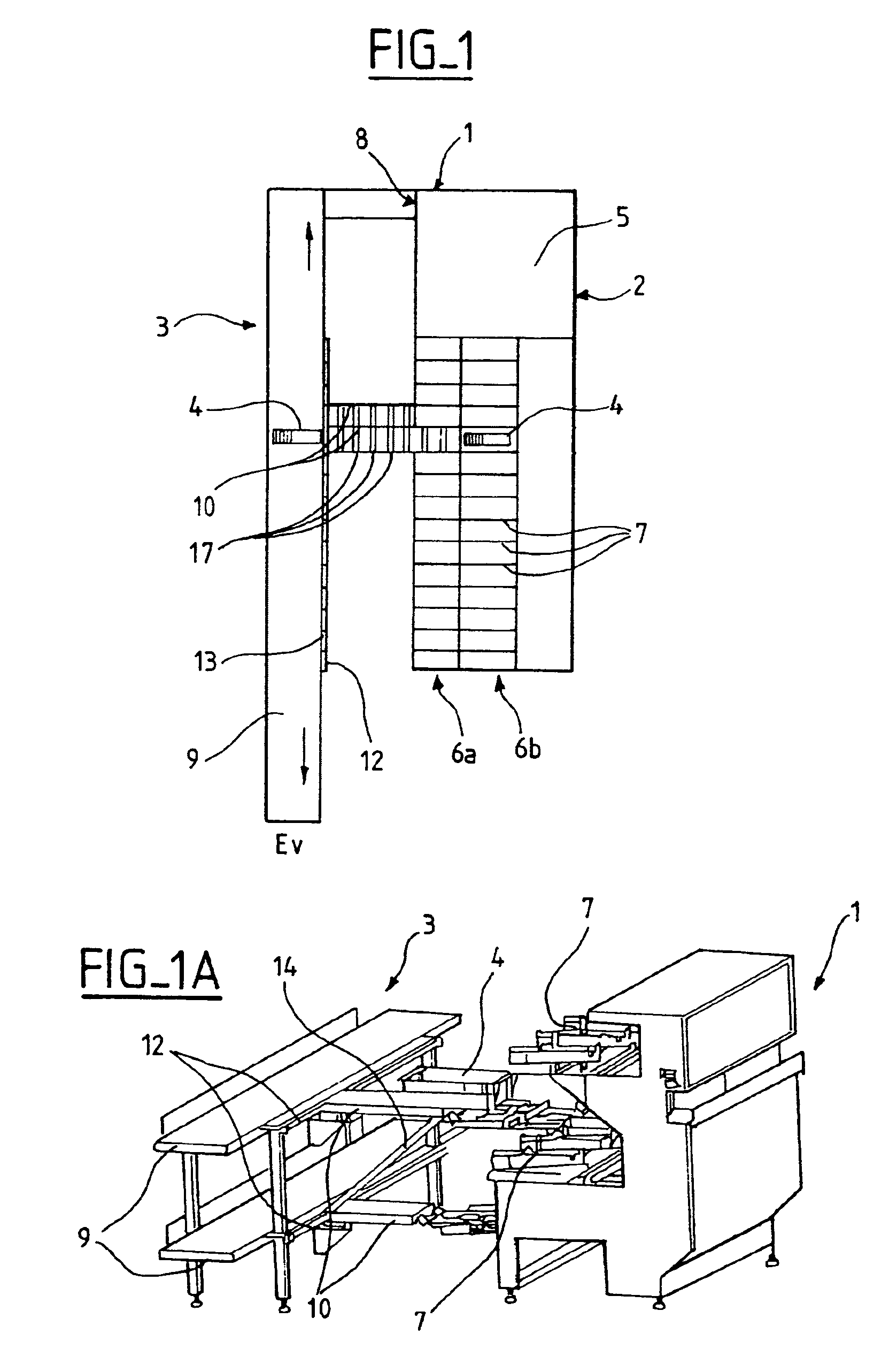
[0021]FIGS. 1 and 1A show a postal sorting machine 1 constituted by a sorting unit 2 and a transfer structure 3 for transferring storage bins 4.

[0022]The sorting unit 2 comprises a unit 5 for receiving and recognizing postal articles, and, in this example, it comprises a unit having two horizontal rows 6a and 6b of sort outlets 7, with bins 4 for storing postal articles in the vicinity of the sort outlets 7 and with the rows being superposed and parallel. The postal articles are inserted into the sorting unit 2 via an inlet 8 of the machine.

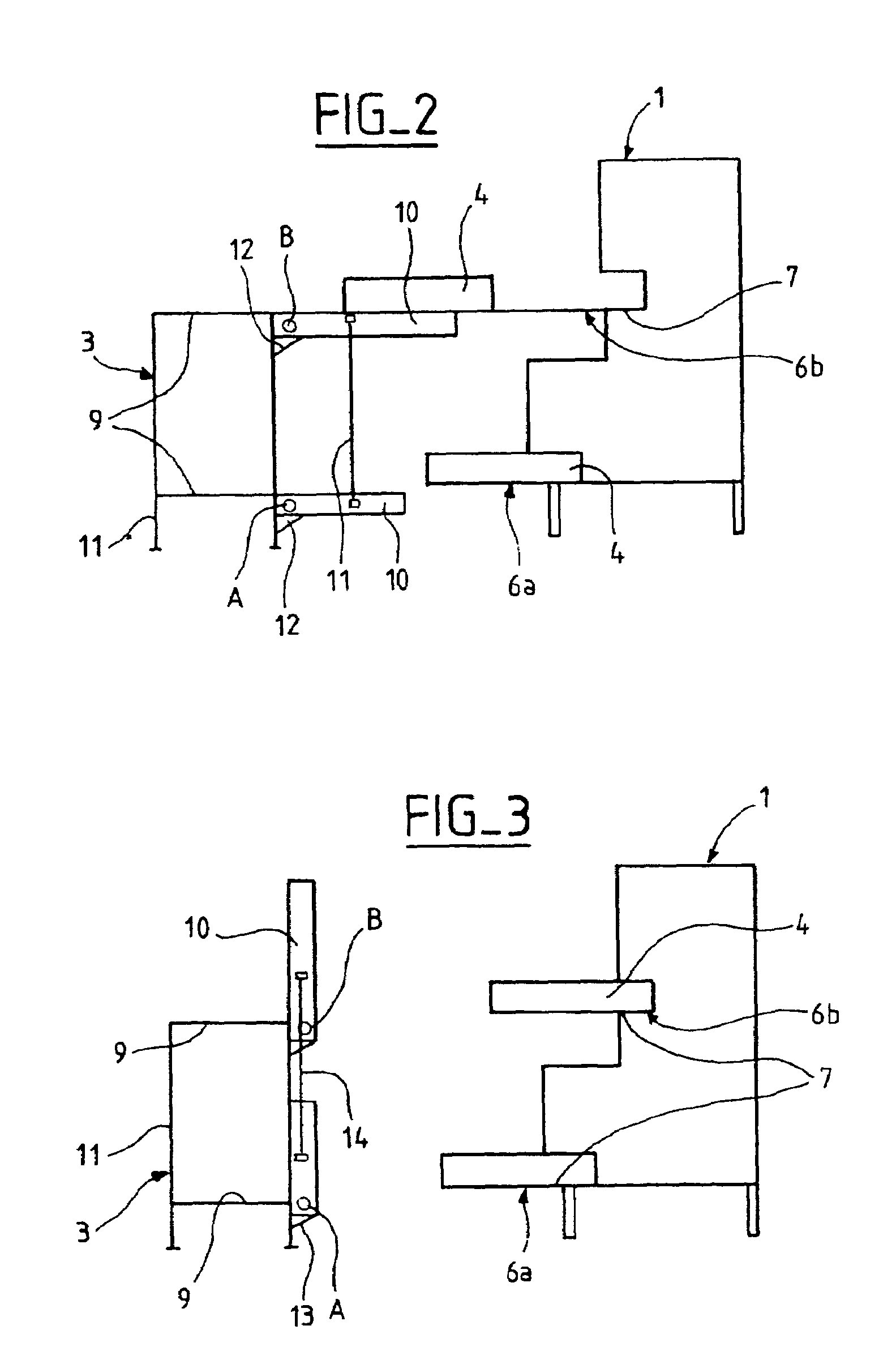
[0023]The transfer structure 3 is made up of two superposed conveyors 9 (more clearly visible in FIGS. 2, 3, and 4), e.g. belt conveyors arranged parallel to the rows 6a and 6b of sort outlets 7, and two gangways 10 (more visible in FIGS. 2, 3, and 4) that are movable along the rows of sort outlets, each being disposed between one of the rows 6a, 6b of sort outlets 7 and a conveyor 9. The conveyors 9 are both-way conveyors extending between the i...


PUM


Abstract

A postal sorting machine (1) comprises sort outlets (7) distributed in one or more horizontal rows that are superposed and parallel. A bin transfer structure (3) is placed along said rows of sort outlets (7), said transfer structure (3) comprising one or more superposed bin conveyors (9) extending parallel to respective rows of sort outlets and one or more superposed gangways (10) that are movable along the rows of sort outlets (7), each extending between a row of sort outlets (7) and a corresponding bin conveyor (9) to enable at least one storage bin (4) to be transferred from a sort outlet (7) to a corresponding bin conveyor (9).

Description

BACKGROUND OF THE INVENTION[0001]The present invention relates to a postal sorting machine having sorting outlets distributed over one or more horizontal rows that are superposed and parallel, and in which each sorting outlet is provided with a bin for storing postal articles. The invention extends to so-called two-sided sorting machines having sorting outlets on both of two sides.[0002]The invention applies most particularly to a machine working in one or more passes in order to sort postal letters, and it relates in particular to a sorting machine capable of preparing postal delivery rounds or “walks” in one, two, or three passes. More particularly, the invention applies to a sorting machine capable, in two passes, of preparing about one hundred delivery rounds, or more depending on the number of sort outlets.[0003]At present, in order to prepare delivery rounds, postal articles are inserted for a first pass into the sorting machine and are sorted a first time into sort outlet rec...

Claims


Application Information

Patent Timeline
Patent Type & Authority Patents(United States)
IPC IPC(8): B07C3/00B65G37/00
CPCB07C3/008
Inventor GUY, FORELLAFRANCOIS, GILLET
Owner SOLYSTIC
Why Eureka
Try Eureka