WIFI antenna of the clover-leaf or skew-planar wheel type for a drone

a drone and clover-leaf technology, applied in the field of radio, can solve the problems of linear polarization, sporadic loss of data and commands exchanged, and drawback of irregular radiation pattern, so as to minimize the manual operation of manufacturing

Inactive Publication Date: 2017-12-28
PARROT
View PDF0 Cites 2 Cited by
  • Summary
  • Abstract
  • Description
  • Claims
  • Application Information

AI Technical Summary

Benefits of technology

[0019]A first object of the invention is to compensate for the drawbacks of the wire structure, which is that of the antennas of this particular clover-leaf or skew-planar wheel type proposed up to now, by proposing such an antenna that is adapted for a heavy industrial mass-production, minimizing the manual operations of manufacturing of the antenna itself and of mounting of the latter in the drone.
[0020]Another object of the invention is to design such an antenna structure whose reduced size allow it to be easily integrated into the thickness of the wings or the arms of a drone, without any protruding element that would increase the drag of the drone, and that does not represent a significant mass liable to needlessly make the drone heavier.

Problems solved by technology

Indeed, the volumes of data transmitted are significant, in particular due to the very high need in video bitrate of the downlink, so that any degradation of the quality of the radio link will have an impact on the quality of the transmission and on the radio range, with a risk of sporadic losses on the data and the commands exchanged.
This dipole-based structure of antenna has however for drawback a rather irregular radiation pattern, having in particular gain dips in the dipole axis.
Moreover, the dipoles produce by nature a linear polarization, which is not optimal in the case where the remote-control device implements antennas of the patch type that, by nature, are circularly polarized.
They are however relatively fragile structures that are delicate to make (due to the non-coplanar geometry of the loops), and in any event incompatible with an industrial mass-production.
Today, these latter implement dipole-type antennas for the WiFi, with the various drawbacks exposed hereinabove causing theses antennas based on dipole arrays to be less efficient than the antennas of the clover-leaf or skew-planar wheel type.

Method used


Image

  • WIFI antenna of the clover-leaf or skew-planar wheel type for a drone
  • WIFI antenna of the clover-leaf or skew-planar wheel type for a drone
  • WIFI antenna of the clover-leaf or skew-planar wheel type for a drone

Examples


first embodiment

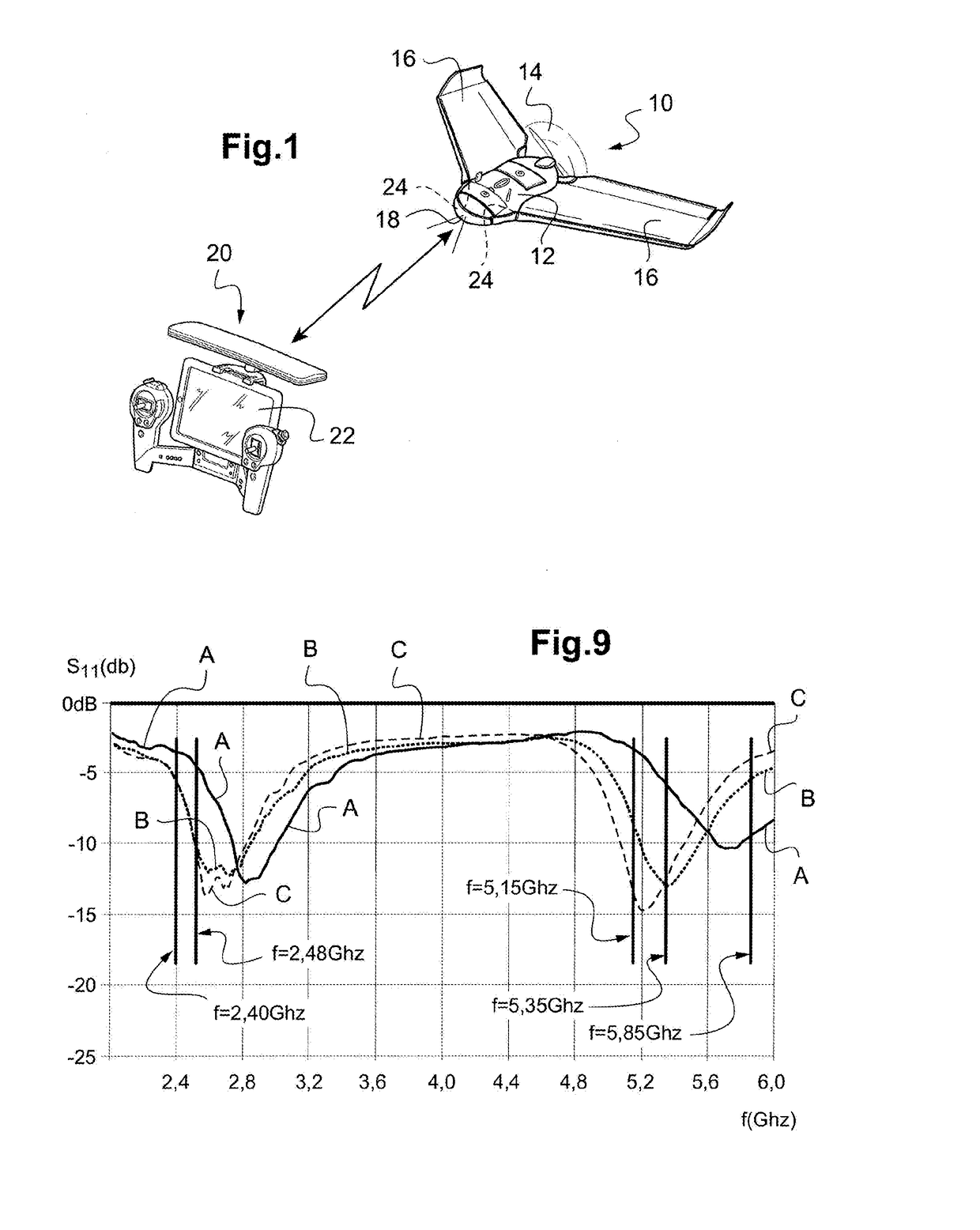
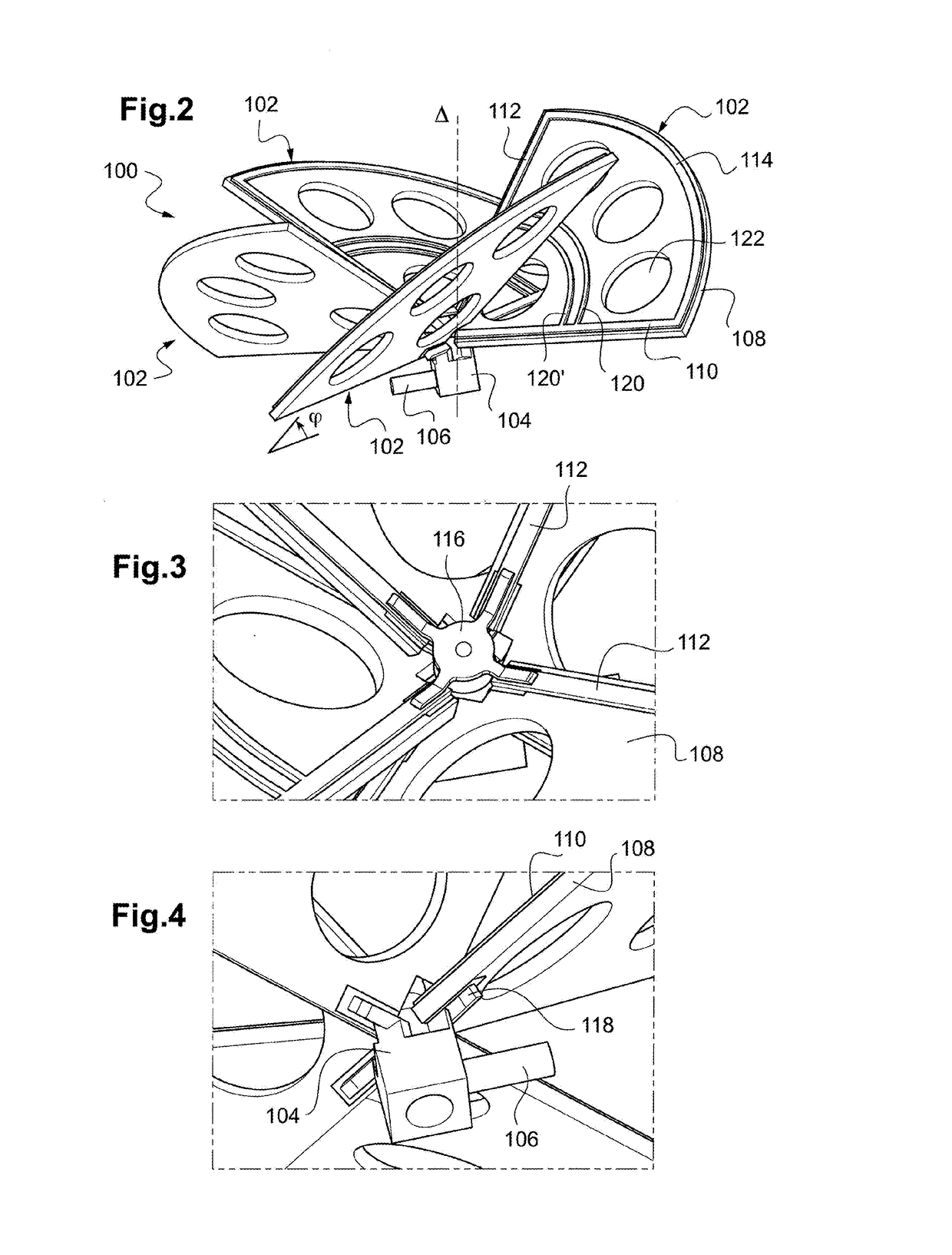
[0050]FIGS. 2 to 4 illustrate an example of the antenna of the invention, which is an antenna particularly well adapted to centimetric frequency bands such as WiFi bands (2.40 GHz-2.4835 GHz and 5.15 GHz-5.85 GHz).

[0051]This application, although being particularly advantageous because responding to precise problems in particular in the field of antennas for drones, is however not limitative, and the configuration of antenna of the invention may be used in other fields, for other applications and in other frequency bands.

[0052]In FIGS. 2 to 4 is illustrated the antenna 100 of the invention, which is an antenna of the so-called clover-leaf or skew-planar wheel type, which comprises a plurality of elementary antennas 102, generally three in number (clover-leaf) or four in number (skew-planar wheel). Each elementary antenna 102 comprises a planar loop extending in a respective plane inclined with respect to the main axis Δ of the antenna, the different loops being non-coplanar and dist...

second embodiment

[0065]FIGS. 5 to 8 illustrate the antenna of the invention, also adapted to a communication in the two WiFi frequency bands.

[0066]In these FIGS. 5 to 8, the same numerical references as those appearing in FIGS. 2 to 4 are used to denote functionally similar elements, which have already been described and which won't be described again.

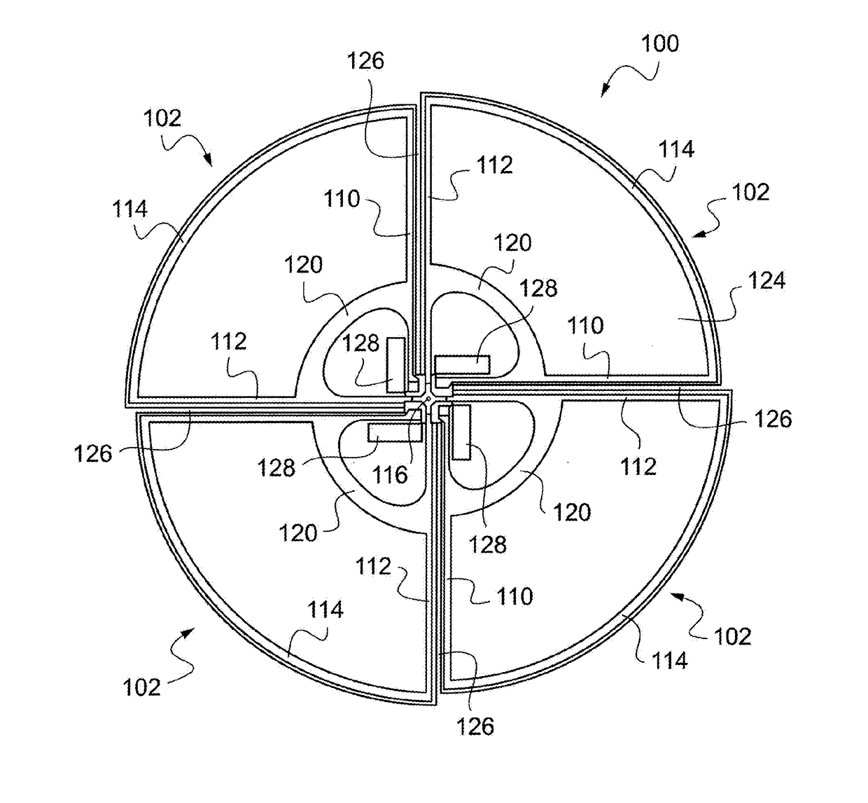
[0067]In this second embodiment, the inclined structure of the conductive pattern defining the loops is formed on a flexible support 124 of the “flex PCB” type, typically made of polyimide.

[0068]This flexible support 124 has approximately the shape of a circular disc, in which have been formed radial notches 126 delimiting four circular sectors of 90° opening (a quarter of a circle), which define and individualize the four elementary antennas 102.

[0069]In the vicinity of the central region of the antenna, the four circular sectors are connected to the central portion 130 by narrow bridges of matter 132 (see in particular FIG. 7), acting as a hinge, tha...


PUM


Abstract

An antenna includes one or more elementary antennas with non-coplanar planar loops extending about a main axis in respective inclined planes. Each elementary antenna is formed by tracks of a structure printed on a circuit support extending in the inclined plane, with two imbricated planar loops tuned on frequencies includes in two respective distinct WiFi frequency bands. With a flexible circuit support, an antenna housing of the drone includes a conformed hollow cavity comprising a plurality of inclined planar faces, which are the counterparts of the inclined planes of the elementary antennas, against which bear these latter after deformation of the flexible support.

Description

CROSS REFERENCE TO RELATED APPLICATIONS[0001]This application claims priority under 35 U.S.C. §119(a) to French Patent Application Serial Number 1655389, filed Jun. 23, 2016, the entire teachings of which are incorporated herein by reference.BACKGROUND OF THE INVENTIONField of the Invention[0002]The invention relates to remote piloting of motorized devices, hereinafter generally referred to as “drones”, in particular flying drones, with rotary wing or fixed wing, and more precisely, to radiocommunication antennas used by these devices for the remote piloting thereof.Description of the Related Art[0003]Typical examples of flying drones are the BEBOP™ of Parrot SA, Paris, France, which is a rotary-wing drone of the quadricopter type, or the DISCO™, also of Parrot SA, which a fixed-wing drone of the flying-wing type. Another type of drone to which the invention may apply is the JUMPING SUMO™, also of Parrot SA, which is a remote-controlled rolling and jumping toy.[0004]Patent Cooperati...

Claims


Application Information

Patent Timeline
Patent Type & Authority Applications(United States)
IPC IPC(8): H01Q1/28H01Q1/22H01Q5/30H01Q7/00H01Q1/38
CPCH01Q1/28H01Q1/38H01Q1/2291H01Q5/30H01Q1/287H01Q7/00H01Q1/286H01Q11/14H01Q21/205H01Q21/24H01Q21/29H01Q5/364H01Q5/42
Inventor MAINGOT, FABRICE
Owner PARROT
Why Eureka
Try Eureka