Paramagnetic oxygen sensing apparatus and method

a technology of paramagnetic oxygen and sensing apparatus, which is applied in the direction of magnetic measurement, material and fluid analysis using sonic/ultrasonic/infrasonic waves. it can solve problems such as insensitive to static pressure and achieve good efficiency

Inactive Publication Date: 2006-07-25
GE HEALTHCARE FINLAND
View PDF9 Cites 16 Cited by
  • Summary
  • Abstract
  • Description
  • Claims
  • Application Information

AI Technical Summary

Problems solved by technology

Thus in passive sensing, piezoelectric crystal is sensitive for alternating pressure, but insensitive for static pressure.

Method used


Image

  • Paramagnetic oxygen sensing apparatus and method
  • Paramagnetic oxygen sensing apparatus and method
  • Paramagnetic oxygen sensing apparatus and method

Examples


Embodiment Construction

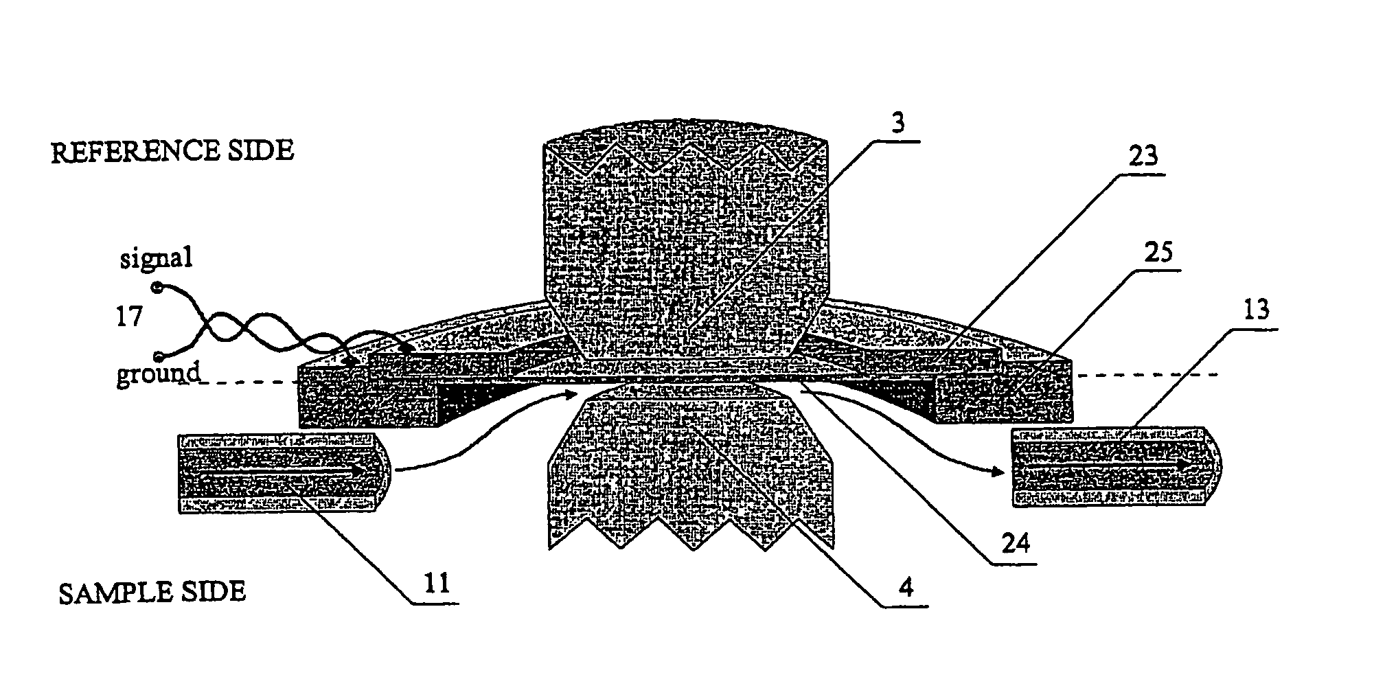
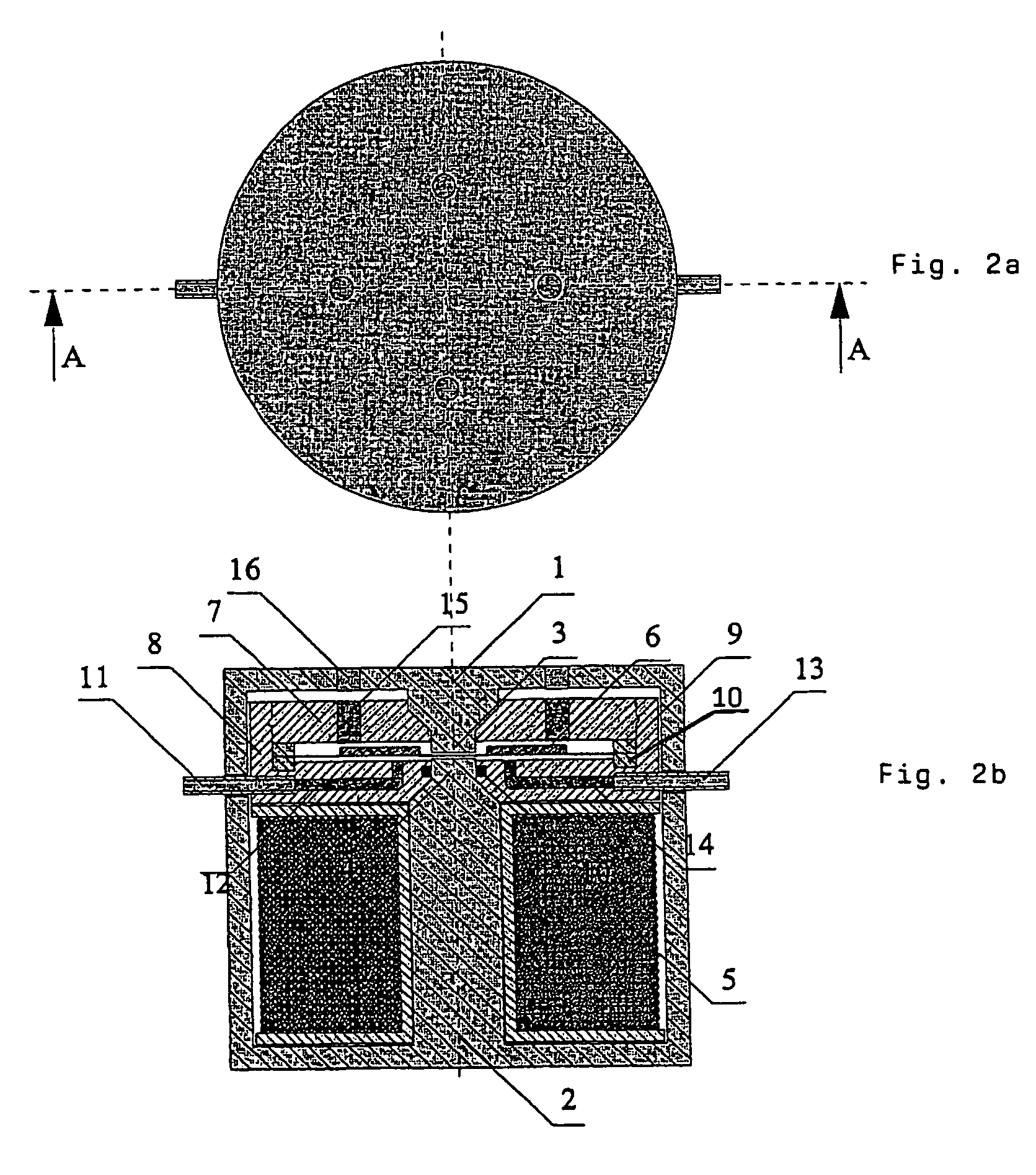
[0021]FIG. 2 shows an embodiment of the oxygen sensing apparatus, which has a thin, disk shaped piezoelectric pressure sensor mounted inside the air gap of an electromagnetic circuit. The electromagnetic circuit has a pot core type body, which divides into upper half 1 and lower half 2. The core is preferably constructed of laminated metal sheets to achieve a strong magnetic field, but iron powders and ferrites may be appropriate as well, when higher frequencies are used. The air gap is formed between two opposite surfaces of upper half center tap 3 and lower half center tap 4. The width of the air gap is approximately 200 μm. The pot core also encloses coil 5, which is used to produce magnetic flux into the electromagnetic circuit. The coil is wound around the center tap of lower half of the pot core.

[0022]The pressure-sensor 6, which is located in the middle of the air gap, divides the air gap into two different sides in a planar direction. Both sides form airtight chambers as the...


PUM

PropertyMeasurementUnit
switching frequencyaaaaaaaaaa
widthaaaaaaaaaa

Abstract

A paramagnetic oxygen sensor and method employs a pressure sensor having a membrane extending through an air gap for a magnetic field. A piezoelectric element is mounted on the membrane. Gas chambers are formed on either side of the membrane. The gas mixture, the properties of which are to be measured, is supplied to one of the chambers. A reference gas is applied to the other chamber. A pulsating magnetic field is provided across the air gap and through the chambers containing the gas mixture and reference gas. The differing responses of the gas mixture and reference gas to the magnetic field deflect the membrane. The deflection of the membrane is sensed by the piezoelectric element. The piezoelectric element maybe operated either in a passive mode or active mode to sense the deflection of the membrane.

Description

CROSS REFERENCE TO RELATED APPLICATION[0001]The present application is the U.S. national stage application of International Application PCT / IB03 / 01052, filed Mar. 14, 2003, which international application was published on Oct. 2, 2003 as International Publication WO 03 / 081225. The International Application claims priority of U.S. Provisional Application No. 60 / 366,876, filed Mar. 22, 2002.BACKGROUND OF THE INVENTION[0002]A paramagnetic oxygen sensor employs the following principles. An atom consists of a nucleus that is surrounded by orbiting electrons. An orbit can be occupied by up to two electrons, and one or more orbits make up an electron shell. In addition, each electron spins around its own axis and has a magnetic moment associated with the electron spin. The magnetic properties of the whole atom are then determined by the combined effect of the spins of all the electrons. Two paired electrons in the same orbit have opposite spins, which cancel their magnetic effects. However...

Claims


Application Information

Patent Timeline
Patent Type & Authority Patents(United States)
IPC IPC(8): G01R33/16G01R33/12G01N27/74
CPCG01R33/16G01N27/74
Inventor HAVERI, HEIKKI
Owner GE HEALTHCARE FINLAND
Why Eureka
Try Eureka