Device for testing printed circuit boards

a printed circuit board and test device technology, applied in the direction of electronic circuit testing, measurement devices, instruments, etc., can solve the problems of large investment expenditure, high cost of testing different printed circuit boards, and high design complexity of test devices

Inactive Publication Date: 2006-07-25
SCORPION TECH
View PDF7 Cites 2 Cited by
  • Summary
  • Abstract
  • Description
  • Claims
  • Application Information

AI Technical Summary

Benefits of technology

[0007]This invention is based on the task of providing a test device of the type specified above, by means of which the costs of testing different printed circuit boards can be reduced.
[0008]In accordance with the invention, the needles on the needle plate are adjustable with regard to their tip alignment, thus, with regard to the pattern of contact points which is contactable by the needle plate. Thus, with only one needle plate, different printed circuit boards can be contacted after corresponding adjustment of the needles. For adjusting the test device to another printed circuit board, the needle plate need no longer be changed, but only its needles need to be changed over to the other contact point pattern. Thus, the operating costs of the test device for testing different printed circuit boards can be considerably reduced and—even without procurement expenditures—individual specimens of printed circuit boards or small series respectively can be inexpensively tested. If the needle plate is correctly adjusted, the individual test procedures for a large series of identical printed circuit boards are performed at the same high speed as according to the state of the art.

Problems solved by technology

However, such test devices are extremely elaborate since they have a multiplicity of needles, only a few of which are being used for a test procedure.
Such test devices are also very elaborate in terms of their design and especially slow because of their low needle speed.
A major disadvantage of known generic test devices is, however, that when testing different printed circuit boards, a separate needle plate with the corresponding needle pattern must be kept available for each type of printed circuit board to be tested.
This requires major investment expenditures.

Method used


Image

  • Device for testing printed circuit boards
  • Device for testing printed circuit boards

Examples


Embodiment Construction

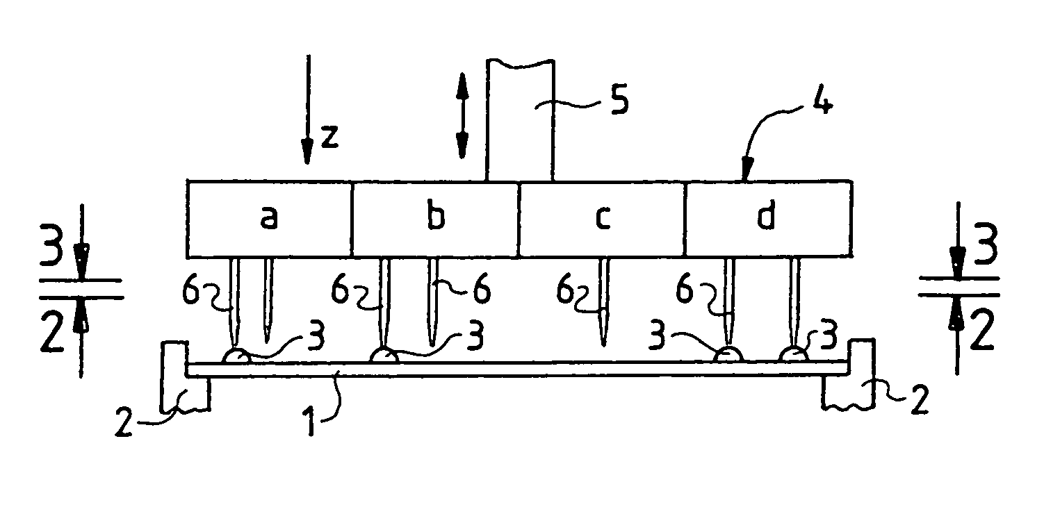
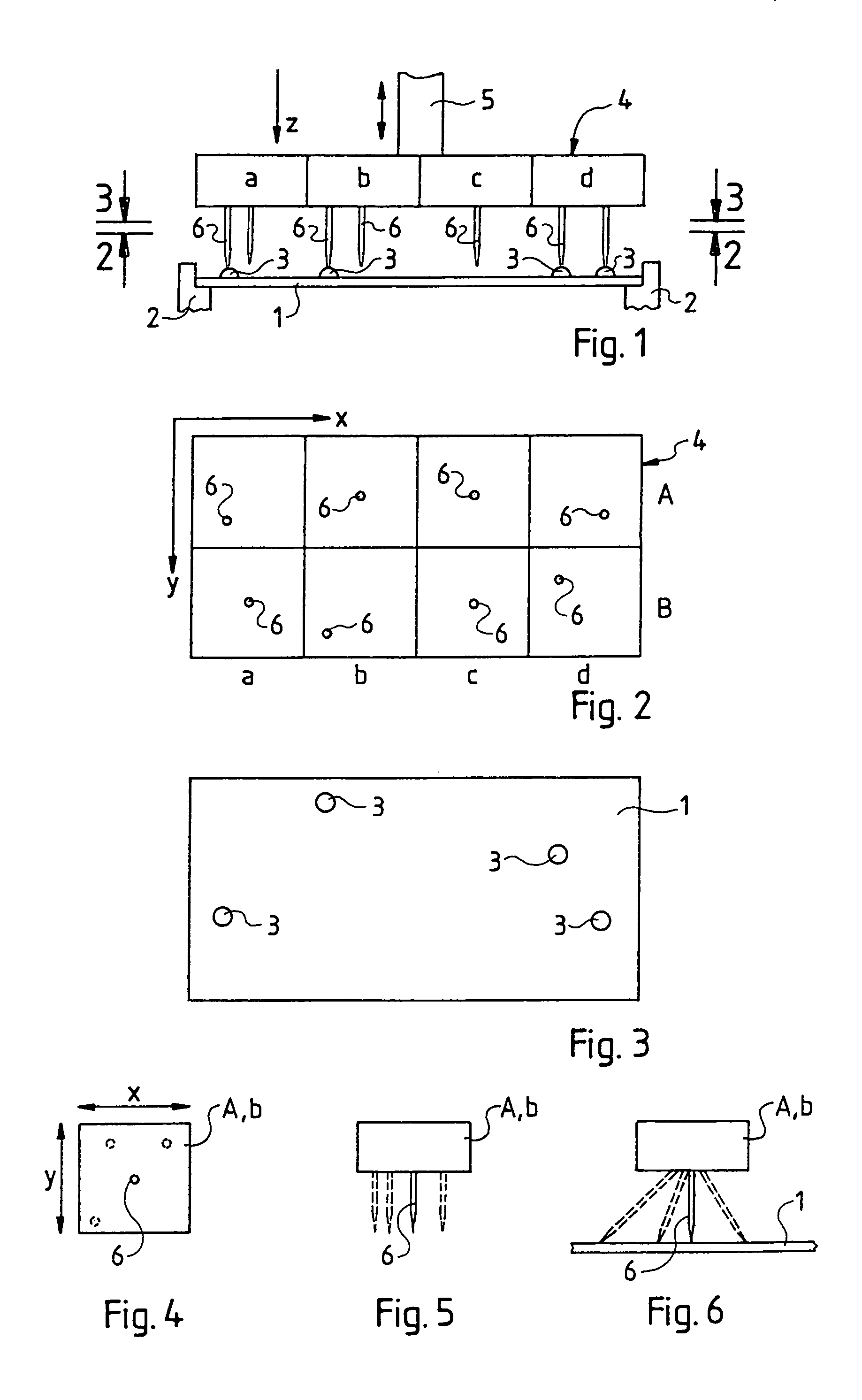
[0020]FIG. 1 shows a device for testing a printed circuit board 1, resting on supports 2 for testing and having on its top side contact points 3 which—as shown in the top view of printed circuit board 1 in FIG. 3—are arranged in a specific pattern on the base surface of the printed circuit board 1. In the embodiment shown, the contact points 3 are represented by roundish raised points. They can be soldering points, for example. For simplification of the drawing, further details of the printed circuit board 1 have been left out, such as e.g. printed conductors, possibly assembled electronic components and the like.

[0021]As shown in FIG. 1, above the printed circuit board 1, a needle plate 4 of a corresponding size is arranged which moves toward the printed circuit board 1 by means of a lifting device 5 movable in the direction of the arrow in the presented z-direction and can again be moved away from it. The printed circuit board 1 bears a multiplicity of needles 6 which are kept, in...


PUM


Abstract

A device for testing printed circuit boards (1) that have contact points (3) arranged in a pattern. The device includes a needle plate (4) that is parallel to the printed circuit board (1) and can be displaced towards the printed circuit board. The plate is equipped with fixed needles (6), whose points are arranged in the pattern of the contact points (3). The needles (6) and their points are arranged so that they can be repositioned in the (x,y) direction of the plane of the needle plate (4).

Description

BACKGROUND OF THE INVENTION[0001]Printed circuit boards consist of an insulating basic material, generally plastic, are provided with printed conductors and are assembled with electronic components by soldering with the printed conductors. They are tested once or several times, e.g. once as a bare printed circuit board and later once again after assembly is completed. For this, they are contacted in a test device with needles at specific contact points among which specific electrical parameters—such as e.g. continuity—are tested via contacting needles and measuring instruments connected thereto. A printed circuit board of the usual design can have several hundred contact points which must be contacted in different combinations for measurement.[0002]The contact points may be places on printed conductors, soldering points or even places on electronic components, such as e.g. legs of ICs.[0003]Since contact points on printed conductors are usually arranged in a specified dot matrix, te...

Claims


Application Information

Patent Timeline
Patent Type & Authority Patents(United States)
IPC IPC(8): G01R31/02G01R1/073G01R31/28
CPCG01R1/07314G01R31/2887G01R1/07392
Inventor ROSKA, GUNTHERHOSSEINI-DEHKORKI, KARIMBUKS, MANFRED
Owner SCORPION TECH
Why Eureka
Try Eureka