Insulated concrete wall forming system and hinged bridging webs

a technology of bridging webs and insulated concrete, which is applied in the direction of load-supporting elements, structural elements, building components, etc., can solve the problems of high energy costs for heating and cooling, time-consuming and wasteful construction types, and the inability to easily form end sections using injection molding processes, etc., to reduce the time of erection of wall forms, reduce waste, and provide rigidity and stability

Inactive Publication Date: 2006-08-01
CANSTROY INT INC
View PDF33 Cites 71 Cited by
  • Summary
  • Abstract
  • Description
  • Claims
  • Application Information

AI Technical Summary

Benefits of technology

[0016]The system uses a bridging web with two end sections embedded in the wall panels and a central section hingedly connecting the end sections. The embedded end sections of the bridging webs are engineered and designed so that they can be mass-produced with a simple injection mold without a need for intermediary complicated procedures for creating a tubular section or hinge. As well, because the bridging web has two hinges, the panels can be collapsed against one another, thus reducing the volume required for transportation.
[0023]A grapnel-type hook at each end of the embedded end-section of the bridging web is in mirror symmetry of a grapnel hook of adjacent row of blocks, which interlocks with the bridging webs of the preceding and following layer of blocks into a stable wall-form unit, eliminating the need to tie the layers together to prevent floating and separation, during placement of concrete, The bridging web-assembly consists of two end-sections and a central-section. The end-sections are embedded opposite each other into each of the polystyrene panels with only the tubular section exposed. The central-section is inserted into the tubular hinge of both end-sections creating two pivoting hinges. The two hinges allow the polystyrene panels to swing, pivot and to be collapsed during transportation or storage. In this way, the volume of the forms can be reduced, allowing for about 40% more forms to be transported for the same price. The forms are assembled after the panels are expelled from the mould.

Problems solved by technology

This type of construction is time-consuming and wasteful in manpower and material resources.
Furthermore, high energy costs for heating and cooling requires that such concrete walls have adequate thermal insulation particularly in regions of extreme climatic conditions.
One disadvantage of this system, however, is that the end sections cannot be easily formed using an injection molding process.

Method used


Image

  • Insulated concrete wall forming system and hinged bridging webs
  • Insulated concrete wall forming system and hinged bridging webs
  • Insulated concrete wall forming system and hinged bridging webs

Examples


Embodiment Construction

[0041]The novel features which are believed to be characteristic of the present invention, as to its structure, organization, use and method of operation, together with further objectives and advantages thereof, will be better understood from the following discussion.

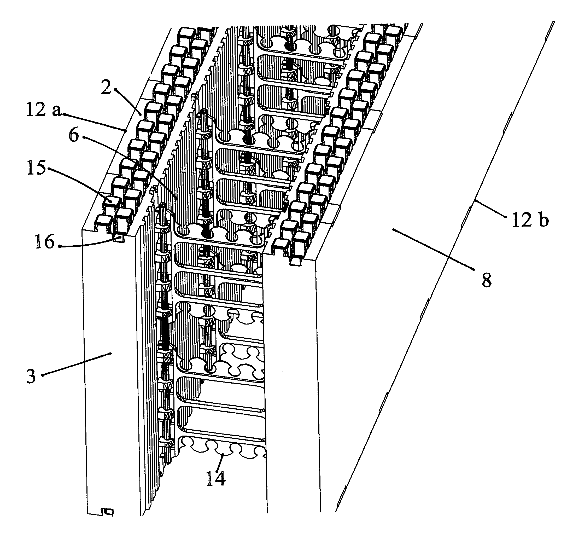
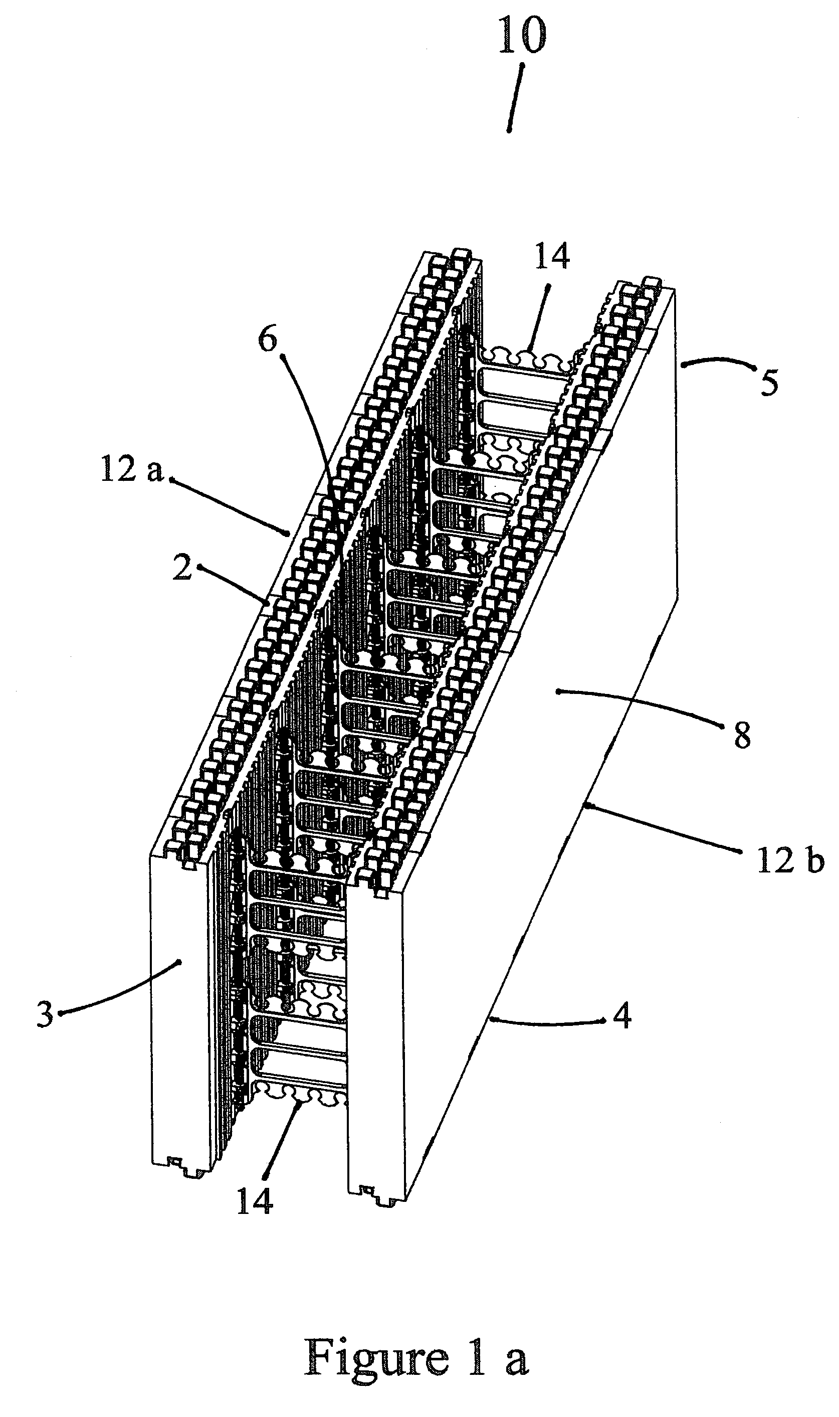
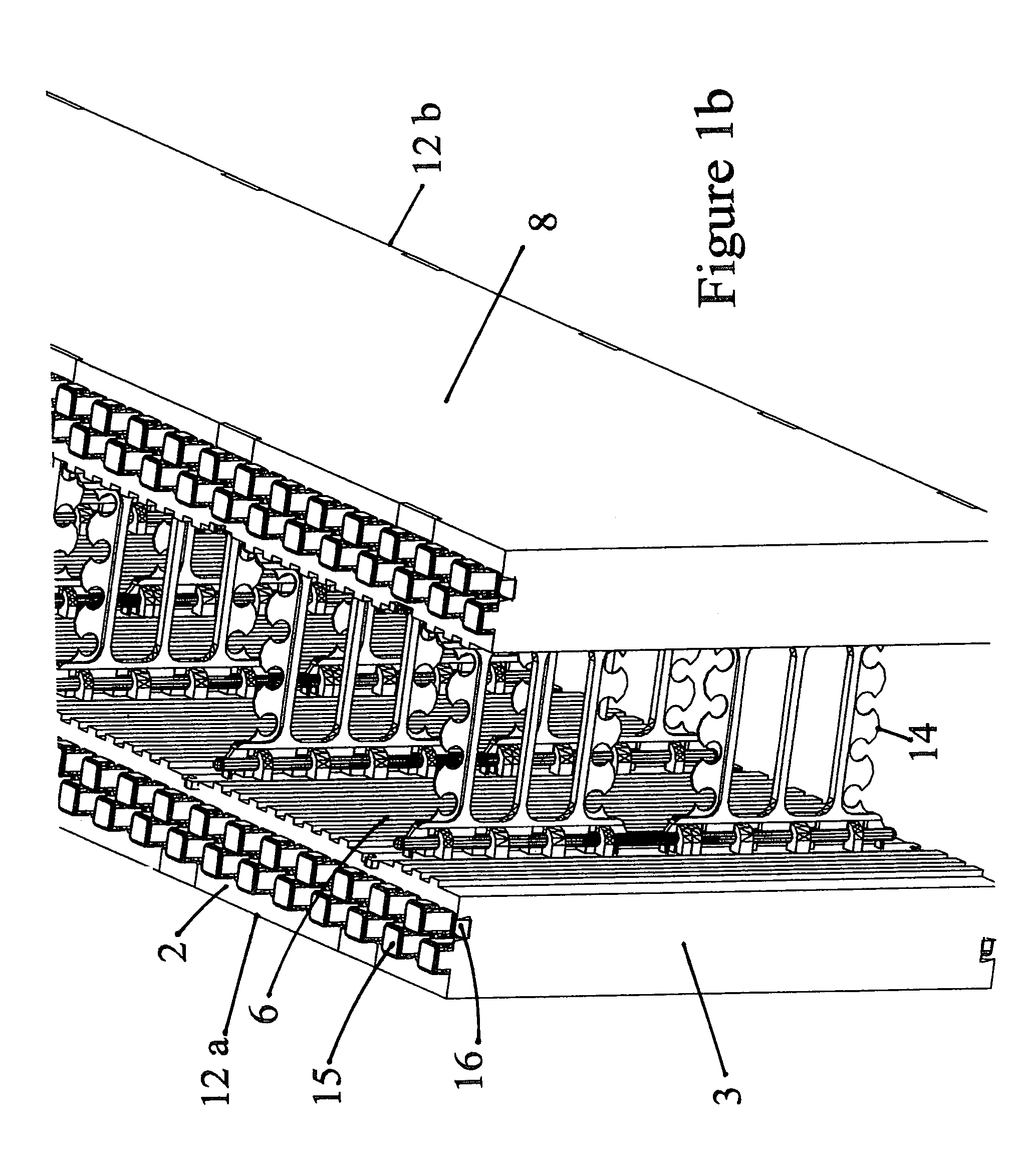
[0042]According to this invention, FIG. 1a is a representative illustration of a discrete wall-form component 10 used in building of wall-forms for placement / receiving material such as concrete. The wall-form obtained is of the type comprising a plurality of wall-form components 10 stacked vertically to form a wall as seen in FIG. 2a and FIG. 2b.

[0043]The wall-form component 10 comprises a first foam panel 12a opposed to a second foam panel 12b arranged in spaced and parallel relationship, and tied together by means of a plurality of bridging webs 14. As illustrated in FIG. 1a, FIG. 1b and FIG. 6, the foam panels 12a and 12b, comprise inner and outer surfaces 6 and 8 respectively, top and bottom surface 2 and 4, respec...


PUM


Abstract

A bridging web for linking a first and second wall panel, the first and second wall panels extending parallel to one another. The bridging web has a first and second end member, each of which extend between a first edge mountable within the wall panels and a second edge. The second edge has a first hinge element. The first end member is mountable within the first wall panel and the second end member is mountable within the second wall panel. A central section extends between a pair of second hinge elements and is mountable between the first hinge element of the first end member and the first hinge element of the second end member. One of the first and second hinge elements is a pin and the other of the first and second hinge elements includes at least one first knuckle and at least one second knuckle. The pin defines a vertical hinge axis. The first knuckle is vertically displaced from the second knuckle, and the first and second knuckles are adapted to bear on opposing surfaces of the pin.

Description

BACKGROUND OF INVENTION[0001]This invention relates to the field of wall-form components for building concrete walls and more specifically, bridging webs which are used to maintain wall-form panels at a specific distance in a parallel relationship to each other.[0002]Conventionally, concrete walls are constructed first by constructing wooden wall-forms and then placing concrete into the space provided between them. Once the concrete hardens, the wooden wall-forms are removed and the walls are insulated and finished as required. This type of construction is time-consuming and wasteful in manpower and material resources. Furthermore, high energy costs for heating and cooling requires that such concrete walls have adequate thermal insulation particularly in regions of extreme climatic conditions.[0003]As a result of continued advancements in the construction industry, many improvements have been introduced in the past several years. New construction materials and building techniques ha...

Claims


Application Information

Patent Timeline
Patent Type & Authority Patents(United States)
IPC IPC(8): E04B2/00E04B2/86
CPCE04B2/8617E04B2002/8694
Inventor TITISHOV, ANTHONY
Owner CANSTROY INT INC
Why Eureka
Try Eureka