A formwork system

a technology of formwork and structure, applied in the direction of structural elements, building components, shaping building parts, etc., can solve the problems of costly transportation, and achieve the effect of increasing or decreasing the spacing between structural panels

Active Publication Date: 2017-09-07
TWINWALL ICF
View PDF64 Cites 9 Cited by
  • Summary
  • Abstract
  • Description
  • Claims
  • Application Information

AI Technical Summary

Benefits of technology

[0025]The first and second end connecting portions are ideally formed as sockets for receiving, by way of a slide fit the third adjust

Problems solved by technology

A problem which has existed was that associated with the storage and transportation of these formworks prior to deployment at a building site.
D

Method used


Image

  • A formwork system
  • A formwork system
  • A formwork system

Examples


Embodiment Construction

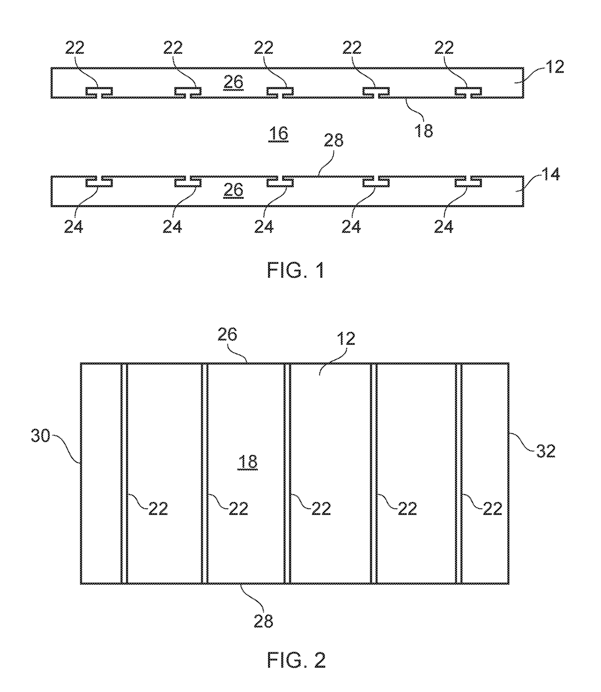
[0033]A system 10 for construction of formwork is shown in the Figures where a settable compound is pourable into a cavity in the formwork and retained by the formwork to set to form a completed structure.

[0034]Referring to FIGS. 1 and 2, the system comprises first and second structural panels 12, 14 arranged to be connected together by connectors (shown in FIGS. 3 to 9) for forming a cavity 16 between the panels. When the panels are fixed in relative orientation, a settable compound such as concrete can be poured into the cavity and allowed to cure. When cured, the panels can be removed or left in place to provide insulation or finished surfaces.

[0035]The panels in the illustrations are configured for forming a wall of, for example, a residential or commercial building, although the panels may have alternative configurations for forming other structures, such as walls having an aperture for a window or doorway or foundations. In the present example, the structural panels 12, 14 are...


PUM


Abstract

The present invention provides a system 10 for construction of formwork where a settable compound is pourable into a cavity in the formwork and retained by the formwork to set to form a completed structure. The formwork comprises structural panels 12, 14 connected by adjustable connectors 34 for varying the spacing between the panels.

Description

FIELD OF THE INVENTION[0001]The present invention relates to a system for construction of formwork where a settable compound is pourable into a cavity in the formwork and retained by the formwork to set to form a completed structureBACKGROUND OF THE INVENTION[0002]Systems for construction of formwork are known hereto and an earlier known example is disclosed in WO2011 / 138573 (SIFTEK). The earlier patent application shows a system having structural panels connected by connectors to define a cavity therebetween for receiving a settable compound such as concrete.[0003]German Patent Application DE-A-19904431 (Schuller) describes an adjustable length spacer with a scissor arrangement.[0004]Other prior art is disclosed in U.S. Pat. No. 4,765,109 (Boeshart) which shows an adjustable tie includes a pair of straps selectively connected together to form a single tie. Each of the pair of straps has a pair of spaced-apart plates at the outer end which will hold the panel of a wall form therebet...

Claims


Application Information

Patent Timeline
IPC IPC(8): E04B2/86E04C5/16B28B7/30
CPCE04B2/8641B28B7/303E04B2/8617B28B7/306E04B2/8635E04B2/84B28B7/28E04G17/06E04B2002/8694E04C5/168E04B2/86
Inventor HOWORTH, GRAEME CEDRICHOWORTH, MALCOLM CHARLES
Owner TWINWALL ICF
Why Eureka
Try Eureka