
Recording apparatus

a recording device and recording technology, applied in the field of recording devices, can solve the problems of low image quality of recorded output inefficient use of printers, etc., and achieve the effect of reliably detecting the type of recording media

Inactive Publication Date: 2006-08-01
CANON KK
View PDF5 Cites 39 Cited by
  • Summary
  • Abstract
  • Description
  • Claims
  • Application Information

AI Technical Summary

Benefits of technology

[0020]It is an object of the present invention to provide a recording apparatus which maintains the distance between a medium detection sensor and the uppermost recording medium constant regardless of the remaining amount of recording media in a recording-medium storage so as to reliably detect the type of recording media.

Problems solved by technology

The increased number of these instructions due to the increased types of recording media causes a complicated operation for an operator, and the printer cannot warn the operator of the wrong instruction when the operator provides a wrong instruction, thereby sometimes resulting in a recorded output having low image quality.
Also, when a network printer is shared by a plurality of operators and is not installed near some of the operators, the operators are required to go to the printer for checking what type of recording media is stored in a recording medium storage (or storage unit) before instructing the type of recording media being used, thereby causing the printer to be used inefficiently.
In a printer in which a necessary type of a recording medium can be selected from among a plurality of types of recording media, for example, by having multi-stage cassettes installed therein, an operator can realize which type of recording media is stored in which cassette only when the operator actually pulls out the cassettes, thereby causing the printer to be used inefficiently.
However, in this recording apparatus, since a printer driver in a host computer starts in reality to create printing data under certain recording conditions as soon as the starting command for printing is issued, and the data is transferred to the recording apparatus, it is difficult to change the recording conditions halfway through the transport of the recording medium.
When the recording apparatus is designed not to create recording data in a period from the issue of a starting command for printing to the completion of detecting the type of recording media, although there is no need to change the recording conditions halfway through the transport of the recording medium, the recording apparatus has a disadvantage of a prolonged recording time in total.
However, this invention has a disadvantage that when distances of the light-emitting device and the photo receptor from the surface of the uppermost sheet change as the amount of remaining sheets varies, the amount of received light of the photo receptor varies, thereby leading to an unreliable determination about an output and resulting in wrong detection.
The invention set forth in Japanese Patent Laid-Open No. 7-181756 also has a disadvantage that since the color sensor for detecting the type of recording sheets is fixed at a specific location in the cassette, a change in a distance of the color sensor from the surface of the uppermost sheet causes wrong detection.

Method used


Image

  • Recording apparatus
  • Recording apparatus
  • Recording apparatus

Examples


first embodiment

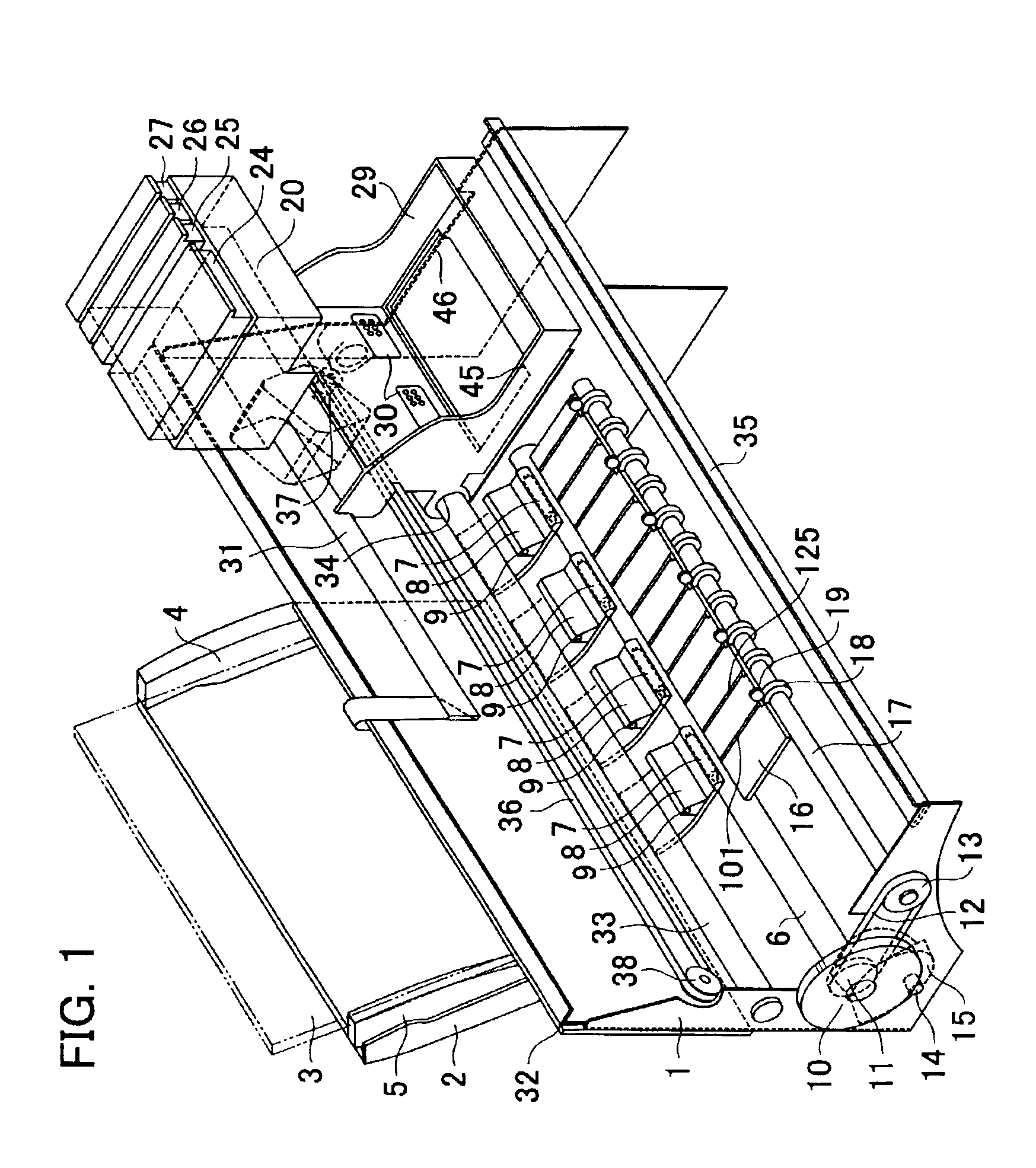
[0033]FIG. 1 is a general perspective view of a recording apparatus according to a first embodiment of the present invention.

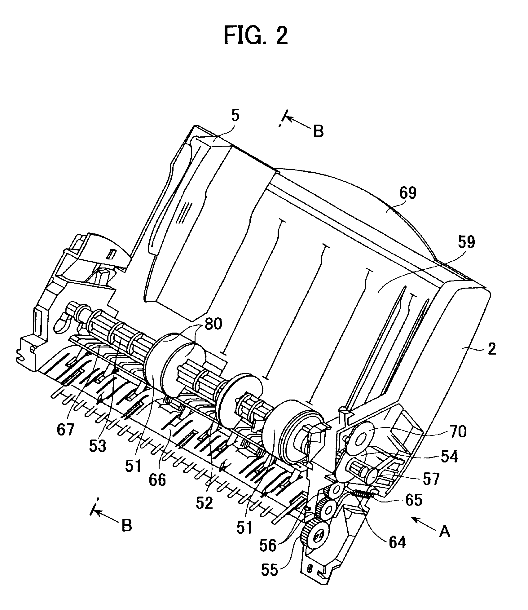
[0034]As shown in FIG. 1, the recording apparatus has a chassis 1, which has a structure for supporting other components, and an automatic sheet feeder (hereinafter, abbreviated to ASF) base 2, which will be described later.

[0035]A sheet fed by the ASF is forwarded to the nips between a line feed (hereinafter, abbreviated to LF) roller 6 and pinch rollers 7. The surface of the LF roller 6 is coated so as to have a predetermined coefficient of friction. Both ends of each pinch roller 7 composed of rubber are rotatably supported by a corresponding pinch roller guide 8 such that the pinch roller 7 rotates freely. The pinch roller guides 8 are rotatable about corresponding rotating shafts 9 and the pinch rollers 7 are urged against the LF roller 6 by corresponding not-shown springs. When the leading edge of the sheet picked up by feeding rollers, which will be des...

second embodiment

[0059]FIG. 8 is a side view of a recording apparatus according to a second embodiment of the present invention, wherein like components as in the first embodiment are omitted.

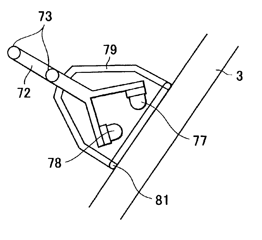
[0060]An ASF base 200 shown in FIG. 8 has the same function as that in the first embodiment. A light-emitting device 201 and a photo receptor 202 detect the type of recording media based on the same principle as that in the first embodiment. The light-emitting device 201 and the photo receptor 202 are supported by a sensor-support slider 203. A shaft of the sensor-support slider 203 is guided by a hole formed in a slider casing 204 so as to move in the direction indicated by the arrow F shown in FIG. 8. The slider casing 204 is fixed to the side surface of the ASF base 200 with screws. The shaft of the sensor-support slider 203 is also inserted into a compression spring 205. The light-emitting device 201 and the photo receptor 202 are surrounded by a hood 207 having rollers 208 disposed at two places on the sid...

third embodiment

[0063]FIGS. 9A and 9B are side views of a cassette of a recording apparatus according to a third embodiment of the present invention, wherein FIG. 9A illustrates a state in which the cassette is loaded and FIG. 9B illustrates a state in which the cassette is unloaded. Recording media 301 are stored in a cassette 300 having therein a pressure-plate spring 302 and a pressure plate 304, which is urged upwards about a fulcrum 303 as a rotating axis. As shown in FIG. 9A, when the recording media 301 are fed, the surface of the uppermost recording medium 301 comes into contact with the surface of a feeding roller 305 by a not-shown cam. When the feeding roller 305 rotates clockwise in FIG. 9A, the recording media 301 are forwarded and only the uppermost one is separated and picked up by a separation claw 306. A light-emitting device and a photo receptor are disposed at the top of a sensor support 307 in the same fashion as in the first embodiment. Since a hood 308 has the same function as...


PUM


Abstract

A reliable detection of optically detecting the type of recording media is achieved. A part of a support member for supporting an optical sensor is pushed against the surface of a sheet by a spring so as to maintain the gap between the sensor and the sheet surface. With this arrangement, a recording apparatus which is free from wrong detection is achieved regardless of a gap-varying factor, that is, the remaining amount of sheets. Also, by arranging a part of a light-shielding hood so as to abut against the sheet, wrong detection due to disturbance light can be prevented.

Description

BACKGROUND OF THE INVENTION[0001]1. Field of the Invention[0002]The present invention relates to a recording apparatus which detects the type of recording media.[0003]2. Description of the Related Art[0004]Hitherto, recording apparatuses such as a printer and a printing machine which perform recording with ink on a recording medium such as a recording sheet have been widely used.[0005]In recent years, the types of recording media have become diversified as the requirements of the market have become more diversified and the recording apparatuses have become more advanced. A variety of recording media, such as a recording sheet whose image quality has been improved by providing an ink receiving layer on the surface thereof, a paperboard such as a postcard having a thickness of at least 0.3 mm, and a piece of cloth which can be recorded on by using a printer, have been commercially used.[0006]Typical recording apparatuses usable for the variety of such recording media are inkjet printe...

Claims


Application Information

Patent Timeline
IPC IPC(8): B41J25/308B41J11/00
CPCB41J11/009
Inventor YAMAMOTO, KOSUKE
Owner CANON KK
Learn More