

Lighted exterior mirror system for a vehicle
- Summary
- Abstract
- Description
- Claims
- Application Information
AI Technical Summary
Benefits of technology
Problems solved by technology
Method used
Image

Examples
second embodiment
[0049]FIG. 27 is an elevation view of the exterior rearview mirror assembly of the present invention;
[0050]FIG. 28 is a bottom plan view of the exterior rearview mirror assembly of FIG. 27;
[0051]FIG. 29 is a plan view of a light module of the exterior rearview mirror assembly of FIG. 28;
third embodiment
[0052]FIG. 30 is a perspective view of the exterior rearview mirror assembly of the present invention;
[0053]FIG. 31 is an exploded perspective view of a signal light of FIG. 30;
[0054]FIG. 31A is a front elevation of a light source of the signal light of FIG. 31;
[0055]FIG. 31B is a side view of the light source of FIG. 31A;
[0056]FIG. 32A is a plan view of a second embodiment of the signal light of FIG. 31;
[0057]FIG. 32B is a plan view of a third embodiment of the signal light of FIG. 31;
fourth embodiment
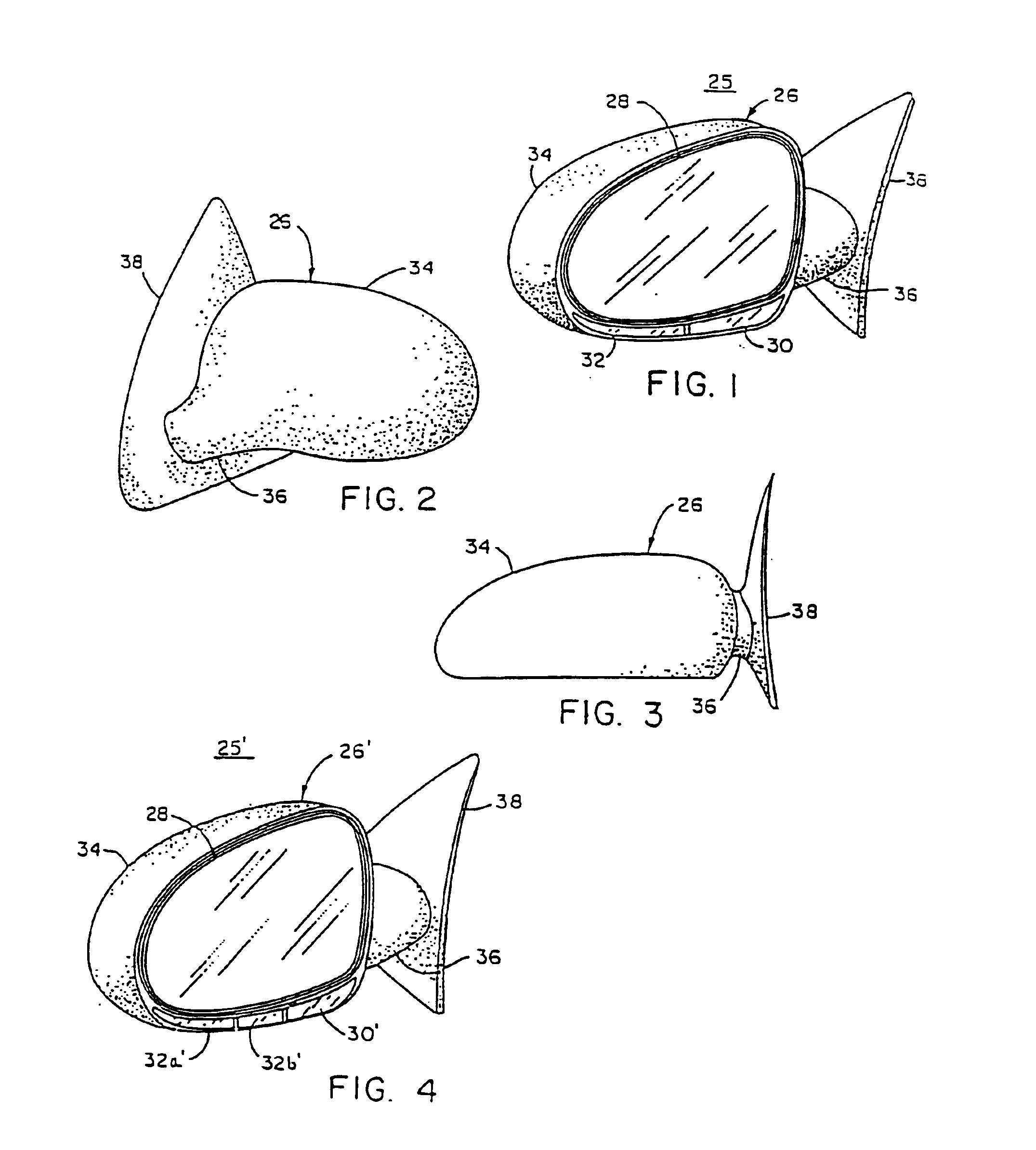
[0058]FIG. 33 is a plan view of the exterior rearview mirror assembly of the present invention shown mounted to a vehicle;
[0059]FIG. 34 is an enlarged plan view of the exterior rearview mirror assembly of FIG. 33 illustrated in a normal extended position;
[0060]FIG. 35 is an enlarged plan view of the exterior mirror assembly of FIG. 33 in a folded position;
[0061]FIG. 36 is a cross-sectional view taken along line XXXVI—XXXVI of FIG. 34 illustrating a light module of the exterior rearview mirror assembly of FIG. 33 and a positioning mechanism for the light module;
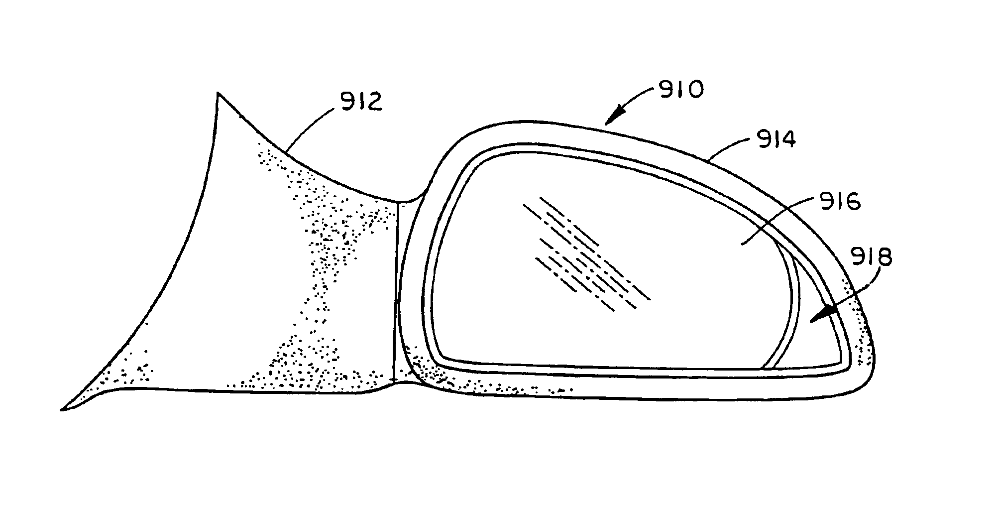
[0062]FIG. 37 is an elevation view of one the exterior rearview mirror assemblies of FIG. 33;
PUM
 Abstract
Description
Claims
Application Information