Formation of glass-based seals using focused infrared radiation

a technology of infrared radiation and glass-based seals, which is applied in the field of glass-based seals using focused infrared radiation, can solve the problems of thermally stable components within the seal, large energy consumption, and short sealing time limits, and achieves the effects of reducing power/energy density, avoiding fractures, and minimizing voids and foaming

Active Publication Date: 2016-11-22
FERRO CORP
View PDF18 Cites 7 Cited by
  • Summary
  • Abstract
  • Description
  • Claims
  • Application Information

AI Technical Summary

Benefits of technology

[0013]2. The use of heat sinks in non-seal areas during the sealing process to prevent overheating of the substrates and attached components. This includes the use of the platens of a heated hydraulic press as heat sinks.
[0021]A second way to reduce the thermal gradients and thereby eliminate fractures from thermal shock and thermal expansion mismatches at interfaces is the use of a so-called ‘tickling’ method. This tickling method entails thermally heating the substrates and seal material below the sealing temperature, then using the localized heating source to heat the seal material above the sealing temperature, resulting in a seal. The problem with the tickling approach is that the whole device is heated to the sub-sealing temperature, and it becomes a pseudo-thermal fire. However, applicants have determined the tickling approach to be very useful in some cases. For one case, it enables the focused IR to seal some higher temperature glasses since it reduces the temperature difference between the sealing material and the substrates, and hence the rate of heat flow. In the case of sealing thin-layer solar cells, it appears that the tickling method can be conveniently combined with the standard EVA lamination step which is typically done at about 150° C. Using a heated press setup, with the press platens heated 150° C. to mimic the lamination step, the press platens still act as a heat sink to prevent the cell components from being exposed to the sealing temperature during the tickling / sealing step.

Problems solved by technology

In addition, since the entire assembly is heated in this process, it requires thermally stable components within the seal and requires considerable energy consumption.
Unfortunately, localized heating approaches come with numerous obstacles to overcome in order to be practical for commercial purposes.
The most significant differences and difficulties compared to thermal sealing are adequate control of the sealing temperature, large ranges of sealing temperatures reached in different sealing areas, very large thermal gradients that commonly cause thermal shock fractures in the seals and / or substrates, and the very short sealing times that limit the amount of glass flow for forming a strong seal.
This is another localized heating approach, and it encounters many of the same obstacles as other localized heating approaches.
With spot-to-spot exposure of high energy packets for very short times, on the order of 100 milliseconds (0.1 sec), extremely large thermal gradients are encountered and there is typically inadequate time to obtain enough glass flow to seal all the gaps in the seal area.
A problem of focused IR sealing with glass-based enamels is reaching the temperatures necessary for melting some of the glass powders.
One of the common problems encountered with many fast-sealing techniques is the formation of voids as well as foaming in the seal material.
This problem is primarily caused by pre-existing voids and by binder burnout in either the as-deposited paste or in the dried paste, when the binder's combustion products and any remaining volatiles have inadequate time to be eliminated from the enamel during the sealing fire.

Method used


Image

  • Formation of glass-based seals using focused infrared radiation
  • Formation of glass-based seals using focused infrared radiation

Examples


example 1

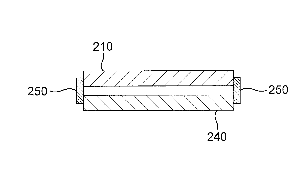
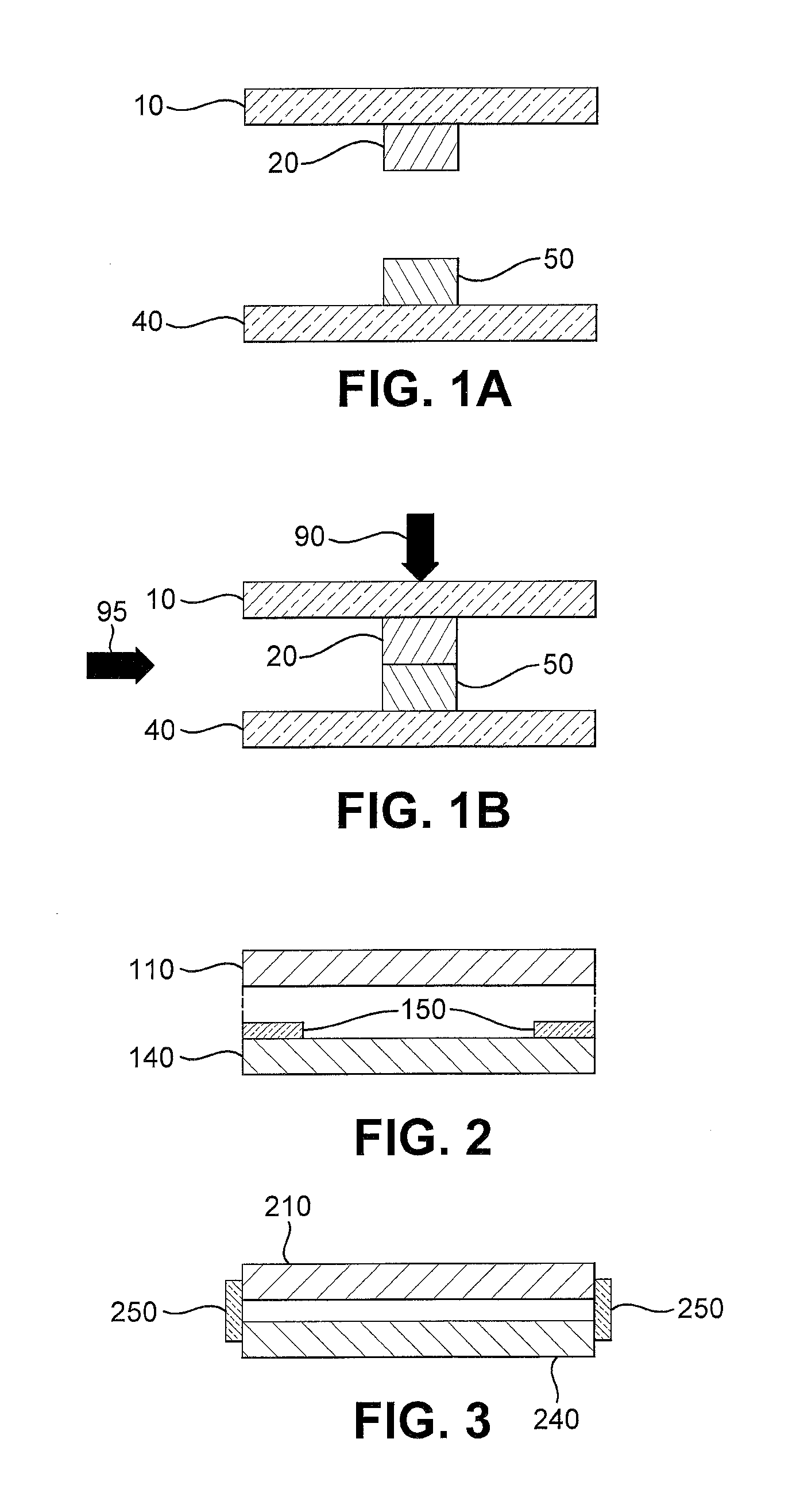
[0087]A bead of low-temperature enamel paste A was applied to a 3″×3″×3 mm glass substrate, dried at 160° C., and then prefired at 350° C. This is conceptually depicted in FIG. 1A, where enamel 20 and / or 50 is applied to at least one of substrates 10 and / or 40. Enamels 20 and 50 are brought into physical contact with one another to form a pre-fired assembly, shown in FIG. 1B. At this point, the pre-fired assembly is irradiated with broadband infrared radiation as disclosed elsewhere herein. In alternate embodiments the irradiation can come through one of the substrates as shown by arrow 90, or from the side (directly incident on the seal material) as shown by arrow 95.

[0088]

TABLE 9Ingredients of Paste A.Paste Awt %Frit A78.31C31 vehicle19.88Byk 410 (thixotrope)0.28Solsperse 38500 (dispersant)1.81Total:100.28

[0089]

TABLE 10Glass Frit compositions of the invention - oxides in mole %OxideFrit AFrit BFrit CLi2O6.88Na2O8.68K2O2.01CaO0.67BaO0.67ZnO11.491.3228.57B2O312.0228.2918.48Al2O31.34...

example 2

[0093]A bead of enamel paste A was applied to a 3″×3″×3 mm glass substrate and dried at 160° C. A blank glass substrate was placed on top of this predried substrate. A thin glass plate was placed below, and two microscope sides were placed on top of this sandwich. The assembly was then placed in a heated press between the metal platens, with the platen temperature set at 320° C. A broadband infrared lamp (2000 W, 10″ lamp focused to a ¼″ line) was used to irradiate the enamel from the side at 100% power for 100 seconds. An assembly is formed with one side sealed. A strongly bonded seal was formed on the edge with no evidence of fractures from thermal shock or thermal expansion mismatch. This example shows that while a prefired enamel may help produce a quality seal by avoiding binder burnout issues, a dried enamel paste can also be used. Likewise, even an as-deposited paste or extrusion can be used directly so long as some spacing material or method is used to prevent excessive spre...

example 3

[0094]An 800 micron high bead of enamel paste B was applied to a 3″×3″×3 mm glass substrate and dried at 160 C. A blank glass substrate was placed on top of this predried substrate. A 3″×3″×0.7 mm glass plate was placed above and below these substrates, the assembly was placed in a heated press between metal platens, and the press heated to 320° C. One edge of the assembly was irradiated using a 2000 W, 10″ broadband IR lamp focused to about a 3 mm height at a setting of 85% power for 5 minutes. The edge was successfully sealed.


PUM

PropertyMeasurementUnit
sealing temperatureaaaaaaaaaa
focal lengthaaaaaaaaaa

Abstract

Broadband infrared radiation is used to heat and fuse an enamel paste to form an enamel seal between at least two solid substrates such as glass, ceramic or metal.

Description

BACKGROUND OF THE INVENTION[0001]1. Field of Invention[0002]Localized heating of glass-enamel frits with infrared and visible / infrared radiation is used to form glass-based seals between substrates, particularly for glass substrates.[0003]2. Description of Related Art[0004]The standard method for the formation of glass-based seals is thermal heating. Thermal sealing is generally a slow process, typically involving heating cycles on the order of 100 minutes, and time at sealing temperature on the order of 20-60 minutes. The cool down part of the cycle is generally slow enough to allow a significant degree of annealing in order to minimize any stress build up in the seals and at the interfaces. In addition, since the entire assembly is heated in this process, it requires thermally stable components within the seal and requires considerable energy consumption.[0005]Some alternate approaches to thermal sealing can be grouped under the concept of localized heating. Localized heating impl...

Claims


Application Information

Patent Timeline
Patent Type & Authority Patents(United States)
IPC IPC(8): C03B23/24C03C27/00C03C8/04C03C8/10C03C8/24C03C23/00C03C3/072C03C3/066C03C3/093
CPCC03B23/245C03C3/066C03C3/072C03C3/093C03C8/04C03C8/10C03C8/24C03C23/001C03C27/00
Inventor MALONEY, JOHN J.ROHN, JR., ANDREW M.KHADILKAR, CHANDRASHEKHAR S.SRIDHARAN, SRINIVASANBLONSKI, ROBERT P.SAKOSKE, GEORGE E.
Owner FERRO CORP
Why Eureka
Try Eureka