Method and apparatus for generating expect data from a captured bit pattern, and memory device using same

a bit pattern and expect data technology, applied in the field of integrated circuit devices, can solve the problems of limiting the overall performance of the computer system, their relatively low speed, and becoming more difficult to maintain synchronization between signals transmitted to the memory devi

Inactive Publication Date: 2006-08-01
ROUND ROCK RES LLC
View PDF282 Cites 10 Cited by
  • Summary
  • Abstract
  • Description
  • Claims
  • Application Information

AI Technical Summary

Benefits of technology

[0023]According to another aspect of the present invention, a packetized dynamic random access memory includes a pattern generator that generates expect data for a repeating bit sequence applied on external terminals of the memory and is utilized in synchronizing clock signals applied to the packetized dynamic random access memory. The pattern generator preferably comprises a register having a plurality of inputs and outputs, and a clock terminal adapted to receive a clock signal. The register shifts data applied on each of its inputs to a corresponding output responsive to the clock signals. A switch circuit has a plurality of first signal terminals coupled to receive latched digital signals from a latch which stores such signals in response to a transition of an internal clock signal. The switch circuit further includes a plurality of second signal terminals coupled to the corresponding inputs of the register, and a control terminal adapted to receive a seed signal. The switch circuit couples each first signal terminal to a corresponding second signal terminal responsive to the seed signal going active. A logic circuit is coupled between the register inputs and outputs, and has a terminal adapted to receive the seed signal. The logic circuit generates, when the seed signal is inactive, new expect data signals on its outputs responsive to current expect data signals provided on the register outputs. A synchronization circuit is coupled to the latch, a clock generator that generates the internal clock signal, and the pattern generator, and operates in combination with the circuits to synchronize the internal clock signal.

Problems solved by technology

This speed disparity limits the rate at which the processor can access data stored in the SDRAMs, which is a common operation, and consequently limits the overall performance of the computer system.
One of the problems of conventional DRAMs is their relatively low speed resulting from the time required to precharge and equilibrate circuitry in the DRAM array.
However, as the rate of data transfer increases, it becomes more difficult to maintain synchronization between signals transmitted to the memory device 16.
Moreover, even if these signals are actually coupled to the memory device 16 in synchronism with each other, they may loose synchronism once they are coupled to circuits within the memory device.
These differences in arrival times can become significant at high speeds of operation and eventually limit the operating speed of memory devices.
The problems associated with varying arrival times are exacerbated as timing tolerances become more restricted with higher data transfer rates.
For example, if the internal clock ICLK derived from the command clock CCLK does not latch each of the packet words CA comprising a command packet CA at the proper time, errors in the operation of the memory device may -result.
Similarly, data errors may result if internal signals developed responsive to the data clocks DCLK0 and DCLK1 do not latch data applied on the data bus DQ at the proper time.

Method used


Image

  • Method and apparatus for generating expect data from a captured bit pattern, and memory device using same
  • Method and apparatus for generating expect data from a captured bit pattern, and memory device using same
  • Method and apparatus for generating expect data from a captured bit pattern, and memory device using same

Examples


Embodiment Construction

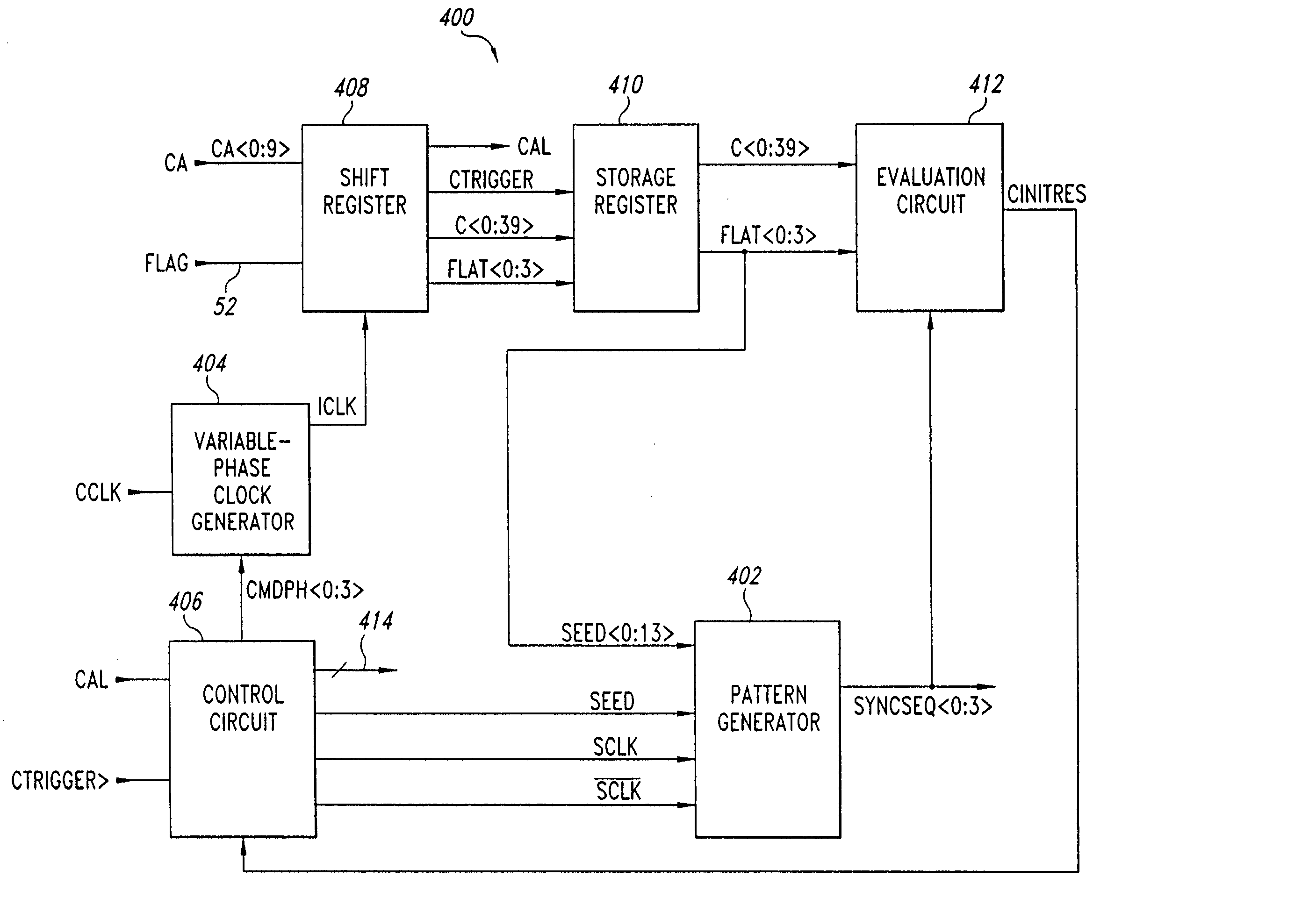
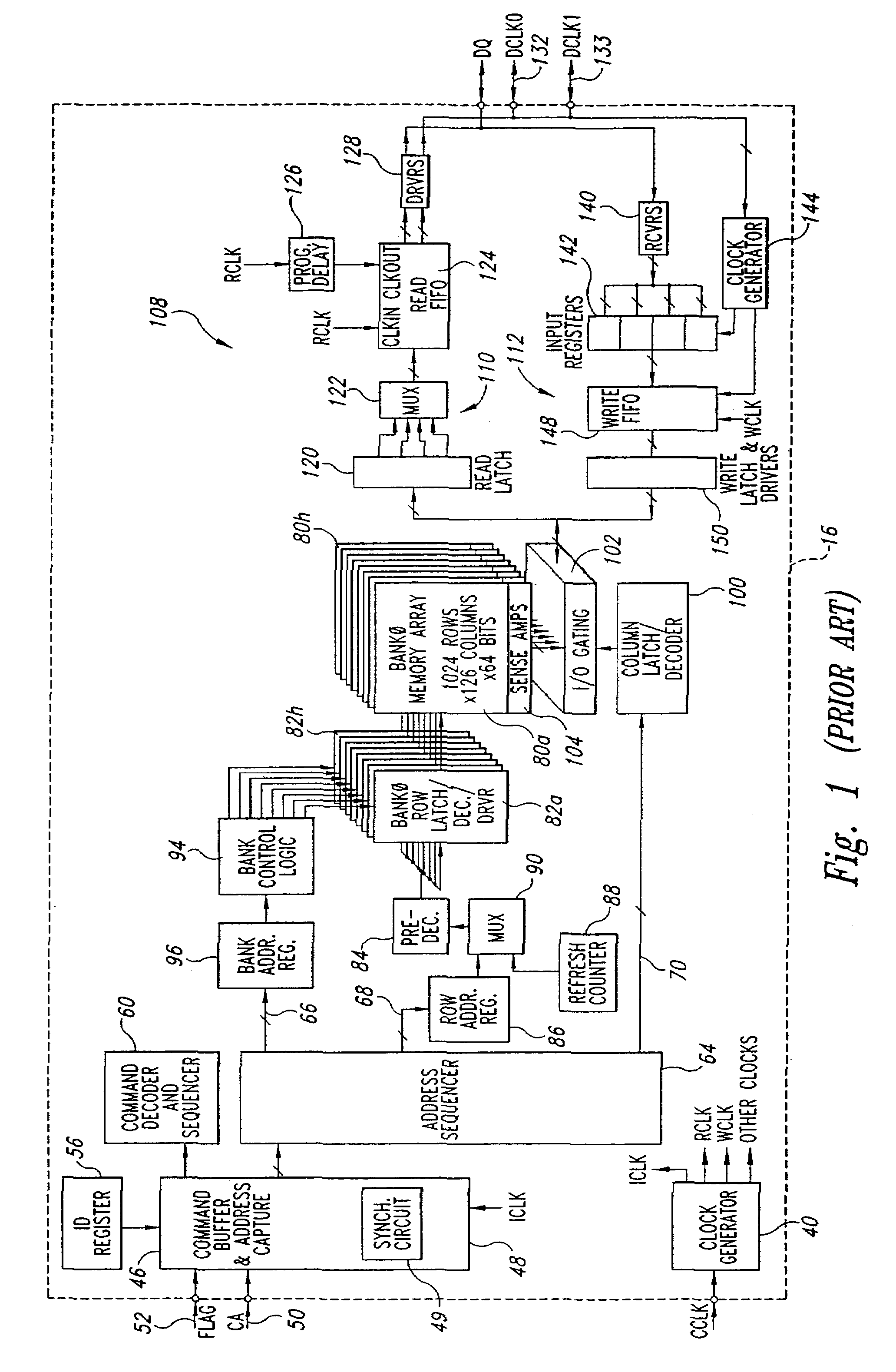
[0036]FIG. 4 is a functional block diagram of a synchronization circuit 400 including a pattern generator 402 according to one embodiment of the present invention. Typically, the synchronization circuit 400 is contained in the command buffer 46, address capture circuit 50, and clock generation circuits 40, 144 of the SLDRAM 16 of FIG. 1, and operates during an initialization mode of the SLDRAM to synchronize the clock signals CCLK, DCLK0, and DCLK1, as will be explained in more detail below. During synchronization of the clock signals CCLK, CLK0, and DCLK1, the pattern generator 402 generates a sequence of expect data words in response to a sample or seed group of bits latched on one of the terminals of the SLDRAM, as will also be described in more detail below. Components and signals that were previously described with reference to FIG. 1 have been given the same reference numbers in FIG. 4, and will not be described in further detail.

[0037]In FIG. 4, only the components of the syn...


PUM


Abstract

Expect data signals are generated for a series of applied data signals having a known sequence to determine if groups of the data signals were properly captured. A first group of the applied data signals is captured, and a group of expect data signals are generated from the captured first group. A second group of applied data signals is then captured and determined to have been properly captured when the second group corresponds to the group of expect data signals. In this way, when a captured series of data signals is shifted in time from an expected capture point, subsequent captured data signals are compared to their correct expected data signals in order to determine whether that group, although shifted in time, was nonetheless correctly captured. A pattern generator generates expect data signals in this manner, and may be utilized in a variety of integrated circuits, such as an SLDRAMs.

Description

CROSS-REFERENCE TO RELATED APPLICATIONS[0001]This application is a continuation of U.S. patent application Ser. No. 10 / 268,351, filed Oct. 9, 2002 now U.S. Pat. No. 6,647,523, which is a continuation of U.S. patent application Ser. No. 09 / 924,139, filed Aug. 7, 2001, issued Nov. 5, 2002 as U.S. Pat. No. 6,477,675 B2, which is a divisional of U.S. patent application Ser. No. 09 / 146,860, filed Sep. 3, 1998, issued Feb. 19, 2002 as Pat. No. 6,349,399 B1.TECHNICAL FIELD[0002]The present invention relates generally to integrated circuit devices, and more particularly to a method and circuit utilizing a first captured bit stream in generating expect data for subsequent captured bit streams.BACKGROUND OF THE INVENTION[0003]A conventional computer system includes a processor coupled to a variety of memory devices, including read-only memories (“ROMs”) which traditionally store instructions for the processor, and a system memory to which the processor may write data and from which the proces...

Claims


Application Information

Patent Timeline
Patent Type & Authority Patents(United States)
IPC IPC(8): G11C29/00G11C7/10G11C7/20
CPCG11C7/1072G11C7/20G11C29/022G11C29/023G11C29/028G11C7/1078G11C2207/2254G11C11/4096
Inventor MANNING, TROY A.
Owner ROUND ROCK RES LLC
Why Eureka
Try Eureka