Method and system for weaving fabrics with two useable sides

a fabric and side weave technology, applied in the field of weaving a fabric, can solve the problems of not being able to weave rib-shaping fabrics, not being able to use rib-shaping fabrics, and requiring two “stem warps”

Active Publication Date: 2006-08-08
VAN DE WIELE MICHEL
View PDF16 Cites 16 Cited by
  • Summary
  • Abstract
  • Description
  • Claims
  • Application Information

AI Technical Summary

Benefits of technology

[0060]In a more preferred embodiment of the fabric according to the invention, the fabric comprises at least one warp thread system with groups of figure warp threads, in which each group comprises a first pair of figure warp threads of a first color, structure or aspect and a second pair of figure warp threads of a second color, structure or aspect, and the two figure warp threads that together are bound in a figure shaping way in the fabric always belong to the same pair, so that a virtually identical figure, drawing or pattern is obtained at both fabric sides. This fabric strongly resembles the aspect of Kelim fabrics.

Problems solved by technology

The disadvantage of this method is, on the one hand, that per woven fabric line (realized per beat of the reed) at least as many weft threads as there are figure shaping weft threads active in that fabric line must be inserted and, on the other hand, that two “stem warps” are required when inserting more than two figure shaping weft threads.
Moreover, it is a well-known fact that figure shaping weft threads are not always very suitable to be inserted as weft threads.
This is in particular the case for weaving machines with air jet insertion, given that not all figure shaping yarn kinds are suitable to be inserted as weft yarn through a shed by means of a jet of air.
As, by this technique, at the figure shaping side, only one weft lies above the stem warp yarn, said technique does not allow weaving of rib-shaping fabrics by positioning multiple wefts above one another, as, in a case like this, we cannot say with certainty which one of both wefts will be figure shaping.
In addition, it is a fact that effect yarns in weft direction cannot be fixed as firmly between the warp threads as effect yarns in warp direction can be fitted between the weft threads.
A disadvantage of such method is increased yarn consumption, on the one hand, due to the requirement for an additional warp thread that will be nowhere visible and, on the other hand, because of the necessity to insert two weft threads per figure shaping loop.
The hereby-created fabric with two useable sides, with figure shaping at both sides, has the disadvantage of comprising two sides with dissimilar properties because of the one-sided rib formation.
In double-sided fabrics with figure shaping threads, we are confronted with the problem that we have to position the threads that are capable of figure shaping in such relation to each other that, at the bottom and at the top of the fabric, the desired figure shaping threads will become visible and the others will remain invisible.
This has as disadvantage that a fabric line can only be added to the fabric after insertion of a number of wefts by an amount that is at least equal to the number of figure shaping weft threads inserted in the fabric line.

Method used


Image

  • Method and system for weaving fabrics with two useable sides
  • Method and system for weaving fabrics with two useable sides
  • Method and system for weaving fabrics with two useable sides

Examples


Embodiment Construction

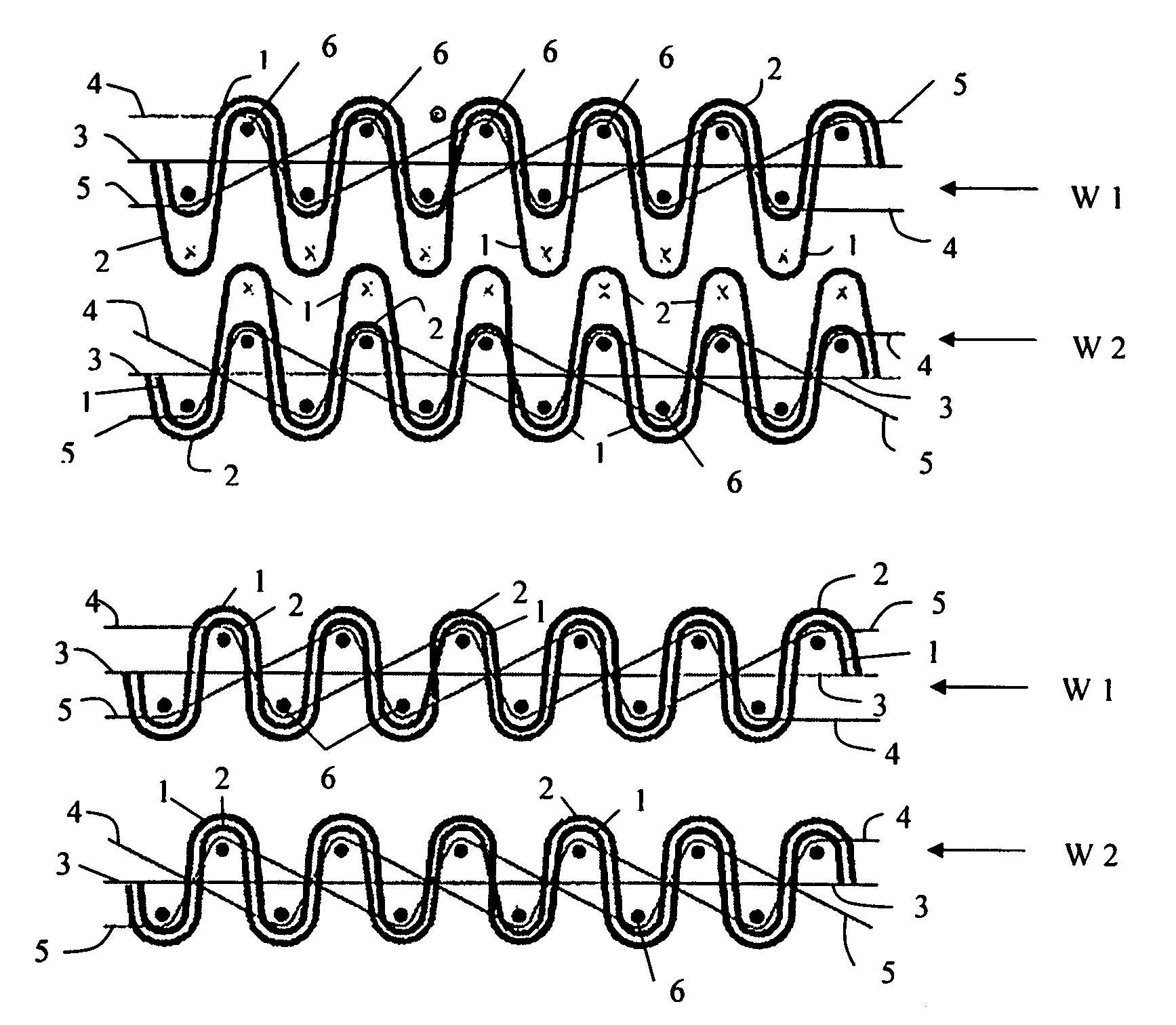
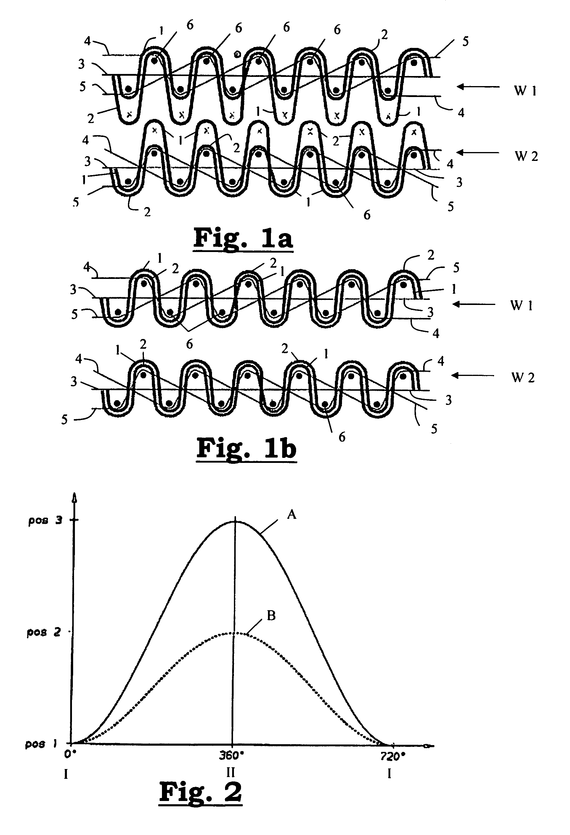
[0081]At the application of the method according to the invention illustrated by FIGS. 1a and 1b, two fabrics (W1), (W2) are woven simultaneously on a weaving machine with two grippers (7), (8). For this, each fabric (W1), (W2) is provided with a series of warp thread systems. Each warp thread system comprises a first figure warp thread (1), a second figure warp thread (2), a tensioning warp thread (3) and a system of two binding warp threads (4), (5) working together. In successive operating cycles of the weaving machine, each time a respective shed is formed between the warp threads (1–5) of the warp thread systems for the upper fabric (W1) as well as between the warp threads of the warp thread systems for the lower fabric (W2). In each operating cycle, two weft threads (6) are inserted at a respective weft insertion level. The upper weft thread (6) is inserted in the shed between the warp threads (1–5) for the upper fabric (W1). The lower weft thread (6) is inserted in the shed b...


PUM


Abstract

This invention relates to a method and to a system for weaving fabrics with two useable sides (W1), (W2), in which per operating cycle one weft thread (6) is inserted, and in which each fabric comprises a first figure warp thread (1) and a second figure warp thread (2) that, in a number of operating cycles, are positioned together alternately above and below the weft insertion level, so that, at both fabric sides, these figure warp threads (1), (2) are bound over the same weft threads (6), while running above one another, and in which the mutual position (upper or lower position) taken up by the first figure warp thread (1) and the second figure warp thread (2) in each fabric (W1), (W2) during the weaving process is determined selectively according to a previously defined figure pattern, preferably by positioning the first (1) and second figure warp threads (2) in a first shed (I) at a first level (POS. 1) at one side of the weft insertion level and in a second shed (II), selectively on a different second level (POS. 2) and third level (POS. 3), at the other side of the weft insertion level. The invention also relates to fabrics (W1), (W2) woven according to such method.

Description

[0001]This application claims the benefit of Belgian Application No. 2004 / 0227 filed May 7, 2004, which is hereby incorporated by reference in its entirety.BACKGROUND OF THE INVENTION[0002]On the one hand, this invention relates to a method for weaving a fabric, characterized in that in successive work cycles of a weaving machine a shed is formed between the warp threads of a number of warp thread systems and one weft thread is inserted in this shed at a weft insertion level, and characterized in that, in each shed, the warp threads are positioned in relation to the weft insertion level in a manner that, together with the inserted weft threads, they form a fabric that displays on both sides figure shaping warp threads and on the other hand, this invention relates to a weaving machine to apply this method according to the invention.[0003]The invention furthermore relates to a weaving machine provided to realize such method as well as to a fabric that on both sides displays figure sha...

Claims


Application Information

Patent Timeline
Patent Type & Authority Patents(United States)
IPC IPC(8): D03D25/00D03D27/06D03D27/10
CPCD03D27/10D03D27/06
Inventor DEBAES, JOHNYSMISSAERT, LUDO
Owner VAN DE WIELE MICHEL
Why Eureka
Try Eureka