Electrical connector for flexible flat cable

a technology of flexible flat cable and electric connector, which is applied in the direction of coupling contact member, coupling device connection, coupling/disconnecting part engagement/disengagement, etc., can solve the problems of increasing manufacturing cost and achieve high rigidity, low rigidity, and increase rigidity

Inactive Publication Date: 2006-08-08
FRAMATOME CONNECTORS INT SA
View PDF9 Cites 24 Cited by
  • Summary
  • Abstract
  • Description
  • Claims
  • Application Information

AI Technical Summary

Benefits of technology

[0016]According to another embodiment of the present invention, the aforementioned second contact beam of the second contact has a high rigidity from the one end that is the actuator-driven portion to the aforementioned attaching portion, and has a low rigidity from said attaching portion to the other end.
[0017]For example, by increasing the rigidity by making the length from the one end that is the actuator-driven portion of the aforementioned second contact beam to the aforementioned attaching portion long, selecting a material with high rigidity, or making the thickness of said second contact beam thicker, a high pressing force can be applied on the actuator-driven portion. Further, by lowering the rigidity by selecting a material with low rigidity for the portion from the aforementioned attaching portion to the other end, or making the thickness of the second contact beam thinner, the second contact point that is the aforementioned other end can respond flexibly to the resistance force from the FPC.
[0019]In addition to the material and elastic force of the aforementioned second contact beam, by giving it a free slanting angle, the contact pressure between the aforementioned second contact point and the FPC can be freely adjusted.

Problems solved by technology

However, according to this structure, when the inserted FPC is gripped, a pressing force due to the actuator is further added to the elastic force of the gripping action contacts, so that it becomes easy for warping to arise in the aforementioned FPC, and four parts, being the contact portions and fixed piece portions of the first and second contact points must be manufactured, so that an increase in manufacturing cost is incurred.

Method used


Image

  • Electrical connector for flexible flat cable
  • Electrical connector for flexible flat cable
  • Electrical connector for flexible flat cable

Examples


Embodiment Construction

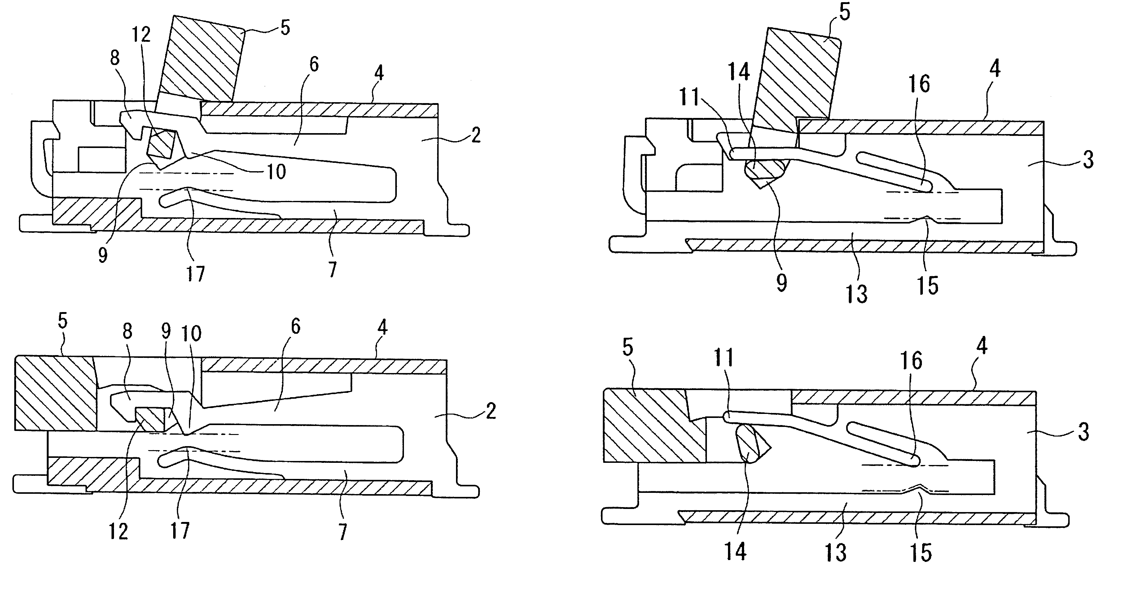
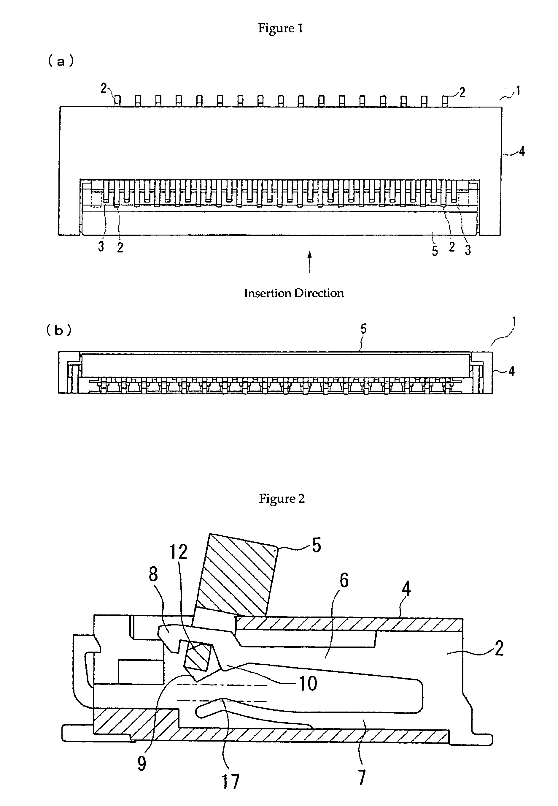
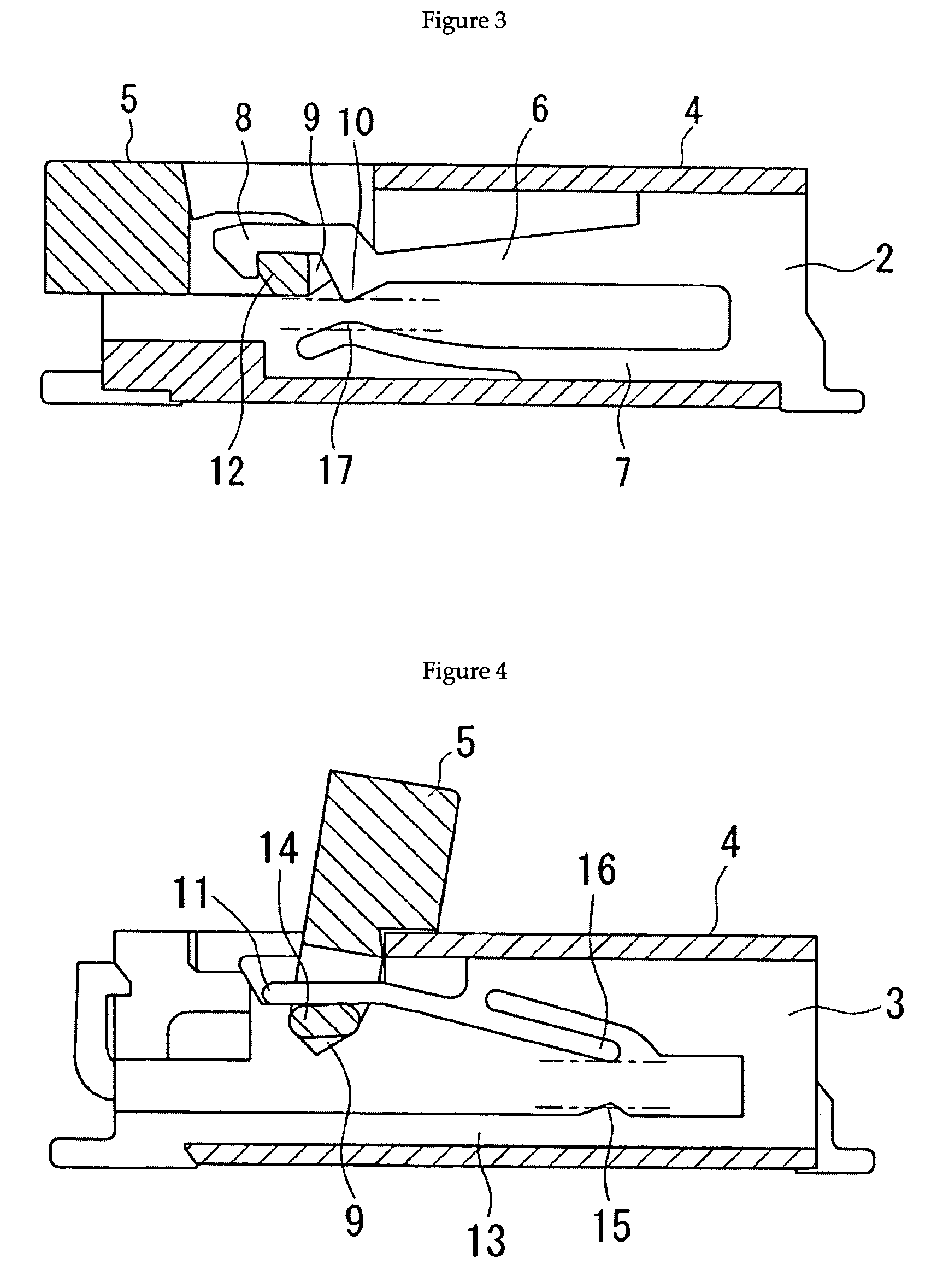
[0044]FIG. 1 shows an embodiment of the electrical connector for FPC according to the present invention. FIG. 1(a) is a top view, and FIG. 1(b) is a front view from the insertion side. Said connector is equipped with two types of metallic contacts 2 and 3, a body 4, and an actuator 5 that rotates around a protruding portion (not shown) formed in the vicinity of both ends in the longitudinal direction on the insertion direction side of said body. The FPC inserted into said connector, represented by alternating long and short dashed lines in FIGS. 2 through 5, has contact points corresponding to the contact points 10 and 16 of the electrical connector 1, and the contact portions of said FPC and the electrical connector are placed in a staggered manner with a space in between in the cable direction.

[0045]FIG. 2 is a side view of an aforementioned metallic contact 2 provided within the body 4 with the actuator 5 open. Said metallic contact 2 is inserted into the opposite side surface fr...


PUM


Abstract

An electrical connector with upper contacts, for a flexible flat cable. The connector is an electrical connector for gripping a flexible flat cable by upper contacts, and the connector includes two kinds of contact members for gripping the flexible flat cable, a housing for receiving the contact members, and an opening / closing type actuator. The contacts of the two kinds of the contact members are spaced from each other in an insertion direction, and the contact members are alternately arranged in the housing so as to form staggered rows of the contacts. With a first kind of contact members, FPC can be inserted without insertion force, and with a second kind of contact members, the FPC can be inserted with low insertion force. The connector is characterized in that is has a zero insertion force (Z.I.F.) and low insertion force (L.I.F.) mechanism structure for insertion of the FPC, where the structure is constructed from the first contact members and second contact members.

Description

TECHNICAL AREA[0001]The present invention concerns an electrical connector that connects flat flexible cables (FPC (Flexible Printed Cable) and FFC (Flexible Flat Cable) and the like are this type of cable, but herebelow in the present specification, they shall be called FPC).BACKGROUND ART[0002]Japanese Unexamined Patent Publication No. 2002-190360 discloses a connector wherein, in a FPC connector having a plurality of contacts which grip terminal portions of printed circuit boards, opposed gripping action contacts and fixed pieces are formed separately. In said connector, the gripping action contacts comprise two types of gripping action contacts with differing lengths, and gripping action contacts with differing lengths are placed so that they are adjacent to each other, so that the contact portions of the ends of the gripping action contacts are placed in a staggered manner. Additionally, fixed pieces affixed to the body at locations corresponding to each of the contact points a...

Claims


Application Information

Patent Timeline
Patent Type & Authority Patents(United States)
IPC IPC(8): H01R13/15H01R12/77H01R12/79H01R12/88H01R13/193
CPCH01R12/774H01R12/88H01R12/79H01R12/77
Inventor OKANO, KAZUYA
Owner FRAMATOME CONNECTORS INT SA
Why Eureka
Try Eureka