Double-sided lens sheet and projection screen

a technology of projection screen and lens sheet, applied in the field of lenses sheet, can solve the problems of inability to precisely determine the position where the characteristics of the photosensitive resin layer change, limited observeable angle, and inability to align the unit lens on the front surface and the back surface, etc., and achieve the effect of reducing the color shi

Inactive Publication Date: 2006-08-08
TOPPAN PRINTING CO LTD
View PDF13 Cites 43 Cited by
  • Summary
  • Abstract
  • Description
  • Claims
  • Application Information

AI Technical Summary

Benefits of technology

[0032]A main object of the present invention is to provide a dual-surface lens sheet such that the color shift is reduced when it is used for a rear projection screen which is used in a displaying device in which a plurality of projector such as three-tube CRT projector are used as light source, it is easy to align the position of the unit lenses on the front surface and the back surface even if the unit lenses are disposed in fine pitch; thus the difficulty in the manufacturing process does not increase.
[0033]Yet, another object of the present invention is, in a micro-lens sheet which is preferable for a lens sheet to be used for a transmission projection screen having two lens sheets in combination particularly with a Fresnel lens, to provide a micro-lens sheet in which the unit lens group is disposed in a pitch as fine as 200 μm or finer, and it is possible to control such that the perspective scope of the emission direction of the display light by the lens section can be wide.
[0034]Yet another object of the present invention is to provide a micro-lens sheet which can easily form a fine BM in which a borderline between an aperture section and the shading section is clear when a BM having a high shading ratio (75%) is formed on a micro-lens sheet away from the lens section.

Problems solved by technology

Thus, observable angle is limited.
In order to produce a dual-surface-lenticular-sheet, alignment in the unit lens on the front surface and the back surface is more difficult.
Therefore, in a case in which the shading pattern is formed by the self alignment method, the position where the characteristics of the photosensitive resin layer changes cannot be determined precisely.
In particular, in a case in which the shading ratio is enhanced so as to realize an image with higher contrast, there is a problem in that it is difficult to form a BM having a clear borderline between a fine aperture section and the shading section when parallel disposition pitch between the unit lens is very fine and each one of the unit lens is fine.
In the micro-lens array, wider perspective angle is necessary; therefore, there are disadvantages such as deteriorated quality in the image due to absorption of light by the diffusion layer and white scattering, and reduced screen gain caused by wide diffusion.
Thus, there is a problem in that cost for parts and manufacturing process become expensive.
Thus, it is not possible to control the perspective angle by independently changing the shape of one of the lenticular lenses.
Therefore, there is a limit for controlling range for the perspective angle; thus, such a limit is not preferable from practical point of view.
However, it is difficult to compatibly realize such depth in lens thug and picture size because of the depth to be molded.
Because of this, even if necessary optical performance can be realized as long as an image area is small, due to a problem in manufacturing process, it is difficult to enlarge the image area.

Method used


Image

  • Double-sided lens sheet and projection screen
  • Double-sided lens sheet and projection screen
  • Double-sided lens sheet and projection screen

Examples


first embodiment

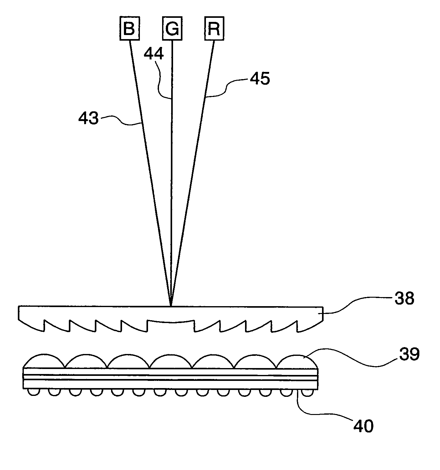
[0107]FIG. 12 is a cross section showing a general structure of a liquid crystal rear projection television. Reference numeral 29 is a light source lamp. Reference numeral 32 indicates an optical structural section. Reference numeral 33 indicates a liquid crystal panel. Reference numeral 34 indicates a first mirror. Reference numeral 35 indicates a projecting lens. Reference numeral 36 indicates a second mirror. Reference numeral 37 indicates a screen. FIG. 13 is a cross section viewed in A—A section in the screen 37.

[0108]In FIG. 13, reference numeral 38 indicates a Fresnel lens. Reference numeral 39 is a micro-lens. Reference numeral 40 is a black matrix section. Reference numerals 43, 44, and 45 indicated light beams which are projected from image projection devices for three-primary colors such as R, G, and B.

[0109]Embodiments of the present invention is explained as follows.

[0110]FIGS. 14A to 14C are views showing dual-lens sheets 30a, 30b, and 30c according to embodiments of t...

second embodiment

[0131]For a second embodiment according to the present invention, it is preferable that a diameter of the unit lens shown in FIGS. 5A and 5B, and its disposition pitch is 200 μm or narrower so as to form a screen which is preferable for observing a fine resolution image.

[0132]Such a fine pitch operation can be obtained by performing a molding operation for forming a lens according to 2P method (photo-polymer method) by using the hardened product of the radioactive-ray-curable-resin.

[0133]In an example shown in FIG. 5, a lens section having aspherical shape with 80 μm diameter is formed on one surface of the transparent supporting member 3 having 1.50 refractive index and 75 μm thickness according to 2P method by using the hardened product of the radioactive-ray-curable-resin.

[0134]In a case of example shown in the above drawings, the maximum width of the chromatic difference of magnification is 6 μm (7.5% to the diameter of lens); thus, it is possible to form BM with 92.5% of shadin...

third embodiment

[0148]Embodiments of a projection screen as an example for the present invention is explained as follows with reference to the drawings.

[0149]FIGS. 8A and 8B are general views for an element lens of a micro-lens sheet used in a projection screen according to the present invention.

[0150]FIG. 9 is a perspective view of an element lens contained in the micro-lens array sheet used in the projection screen according to the present invention.

[0151]FIG. 10 is a cross section of an element lens in a vertical direction contained in the micro-lens array sheet used in the projection screen according to the present invention.

[0152]FIG. 11 is a cross section of an element lens in a horizontal direction contained in the micro-lens array sheet used in the projection screen according to the present invention.

[0153]Here, regarding the lens array sheet shown in this embodiment, the shape of the lens are actually designed, and these drawings are made according to these designed lens shape.

[0154]In FIG...


PUM


Abstract

In order to provide a dual-surface lens sheet in which a color shift is reduced and positions of unit lenses on a front surface and a back surface are easily aligned even if the unit lenses are disposed in fine pitch when used for a rear projection screen which is used for a display device using a plurality of projector as light sources, a half-column-cylindrical-convex-lens is used in a lens sheet having lens sections on front surface and a back surface such that pitch ratio for disposing the unit lenses on the front surface and the back surface is in a range of 1:2 to 1:30 and disposition directions of the lens sections are uniform.

Description

TECHNICAL FIELD[0001]The present invention relates to a lens sheet which is effective when it is used for an image displaying screen (hereinafter called a transmission projection screen, or a rear projection screen) to be used for a rear projection television.BACKGROUND ART[0002]Commonly, in a transmission projection screen, a Fresnel lens sheet and a lenticular sheet are assembled.[0003]FIG. 15 is a general view for a television having conventional three-tube projector. In FIG. 15, reference numerals 51, 52, and 53 indicate image projection devices for colors such as R, G, and B. Reference numeral 54 indicates a mirror. Reference numeral 55 indicates a transmission projection screen.[0004]A Fresnel lens sheet in FIG. 16 emits a light (which disperses from a small-diameter lens) which is projected from a projector to a lenticular sheet 57 as an approximate parallel light by using a converging lens.[0005]The lenticular sheet 57 widens horizontally a range of the projected light which...

Claims


Application Information

Patent Timeline
Patent Type & Authority Patents(United States)
IPC IPC(8): G03B21/60G03B21/56G03B21/62G02B3/00G02B3/06G02B3/08G03B21/00G03B21/10G03B21/625H04N5/74H04N9/31H04N13/04
CPCG02B3/0056G03B21/625G02B3/06G02B3/0068G03B21/62
Inventor EBINA, KAZUYOSHIABE, TAKASHIMIYASHITA, MASARUTAKAHASHI, SUSUMU
Owner TOPPAN PRINTING CO LTD
Why Eureka
Try Eureka