Snowboard binding rotational system with stance adjustment

a rotational system and binding technology, applied in the field of snowboard boot binding systems, can solve the problems of difficult flexibly implementing a hard and soft detent, not conveniently adjustable, and reducing the convenience and fluidity with which the binding may be used,

Inactive Publication Date: 2006-08-15
REYNOLDS DWIGHT H
View PDF19 Cites 21 Cited by
  • Summary
  • Abstract
  • Description
  • Claims
  • Application Information

AI Technical Summary

Benefits of technology

[0009]The present invention provides a rotating binding that allows customizable adjustment of the angle between the hard and soft detent positions with the convenience described above. Generally, this adjustability is provided by use of two selector plates, each supporting one detent, the plates being rotatable with respect to each other and then locked to rotate together. Rotation of a base plate forming another component of the detent allows complete flexibility for the user to choose their stance angle for snowboarding as well as the desired angle for skateboarding, and locking in the snowboarder's selected angle for automatic operation thereafter.

Problems solved by technology

During skateboarding, the angle of the front binding places the user's foot at an awkward angle that may be uncomfortable or promote injury.
While this system provides a simple and intuitive, rapid shifting between skateboarding and snowboarding modes, the predetermined hard-lock and soft-lock detent positions provide a fixed angular separation that may not be right for every user.
While the angle of the binding as mounted on the snowboard may be readily changed during installation, it is not conveniently adjustable, for example, on the slope.
This approach, however, has a significant disadvantage in that multiple detent positions make it difficult to flexibly implement a hard and soft detent.
Further, multiple detents require that the snowboarder carefully select the appropriate detent position each time the snowboard mode is changed significantly reducing the convenience and fluidity with which the binding may be used.
Carelessness in selecting among multiple detents may undesirably change the user's stance angle between snowboarding runs.

Method used


Image

  • Snowboard binding rotational system with stance adjustment
  • Snowboard binding rotational system with stance adjustment
  • Snowboard binding rotational system with stance adjustment

Examples


Embodiment Construction

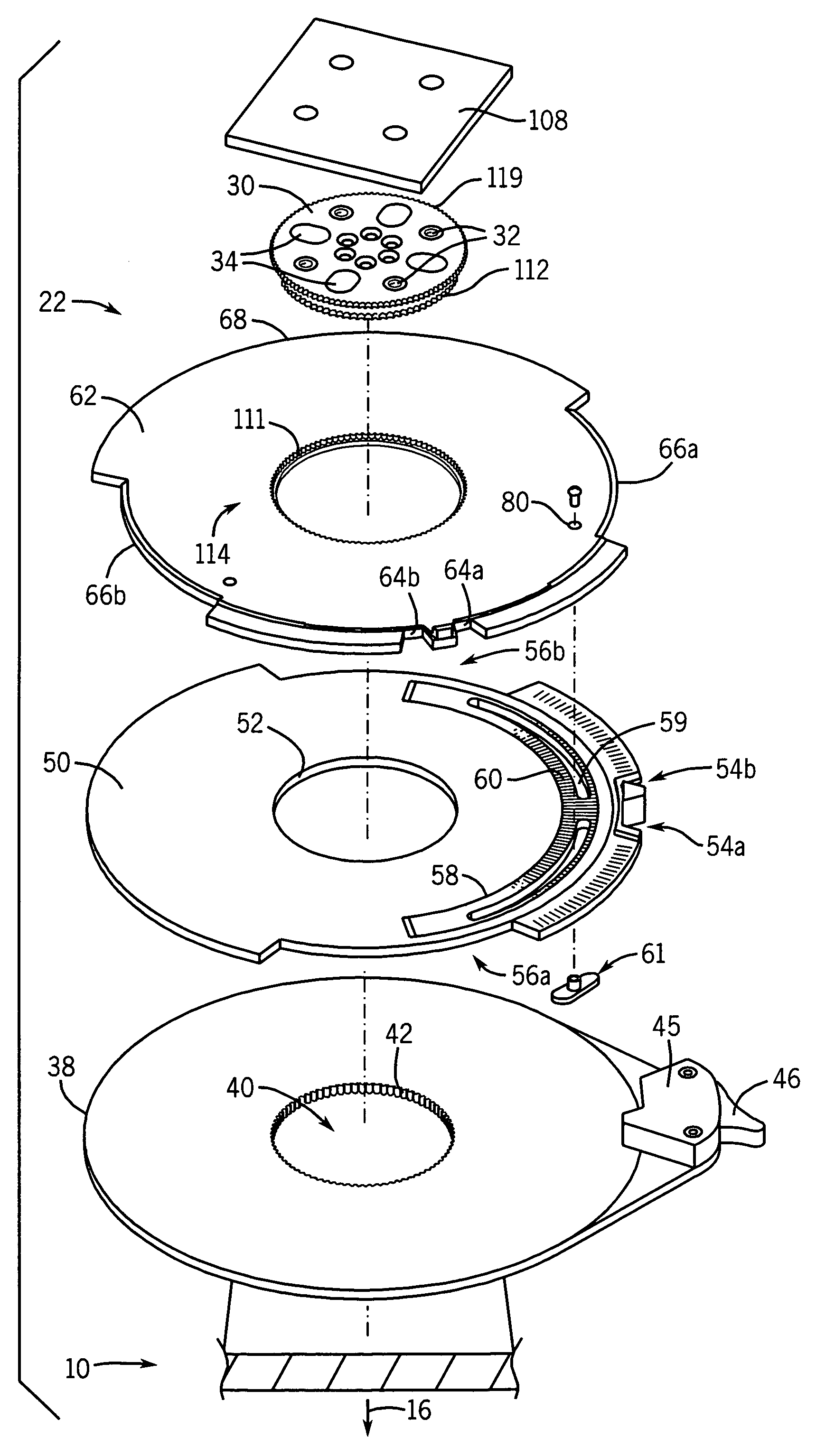
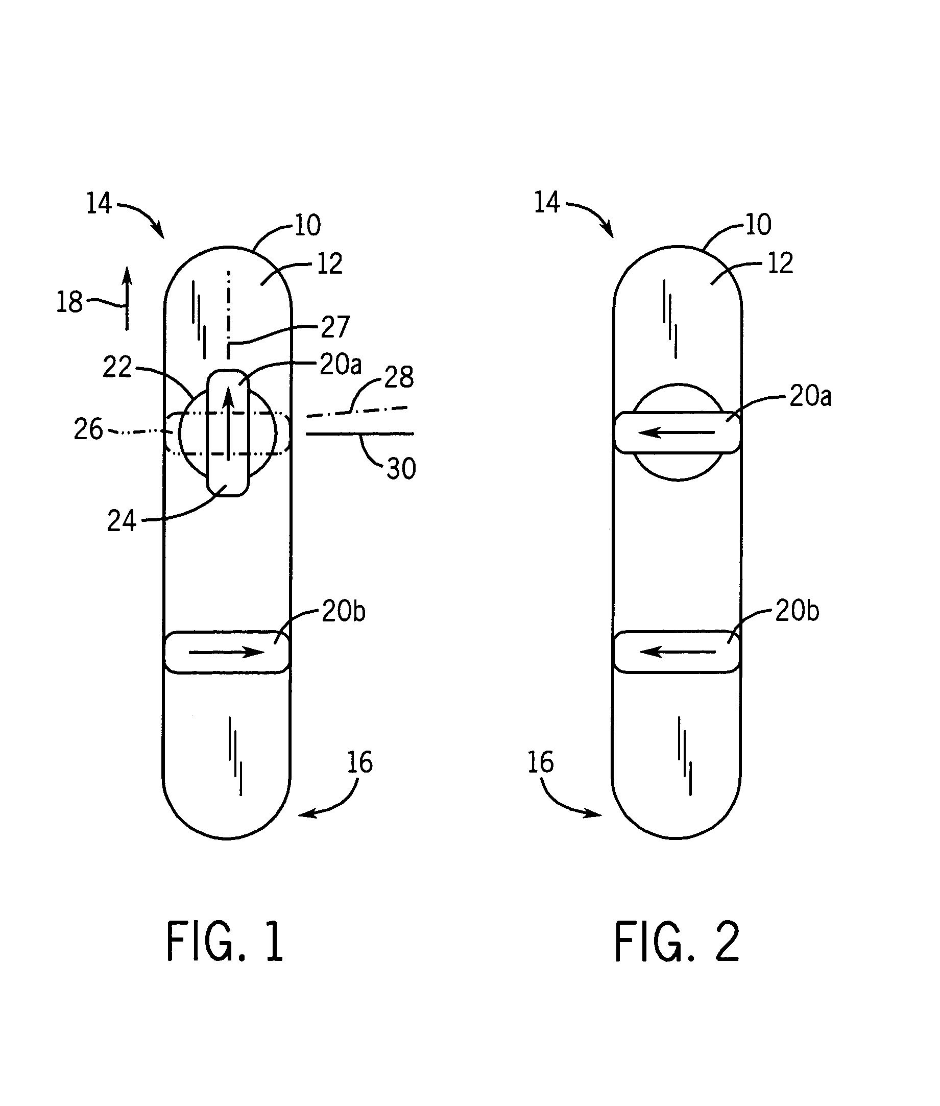
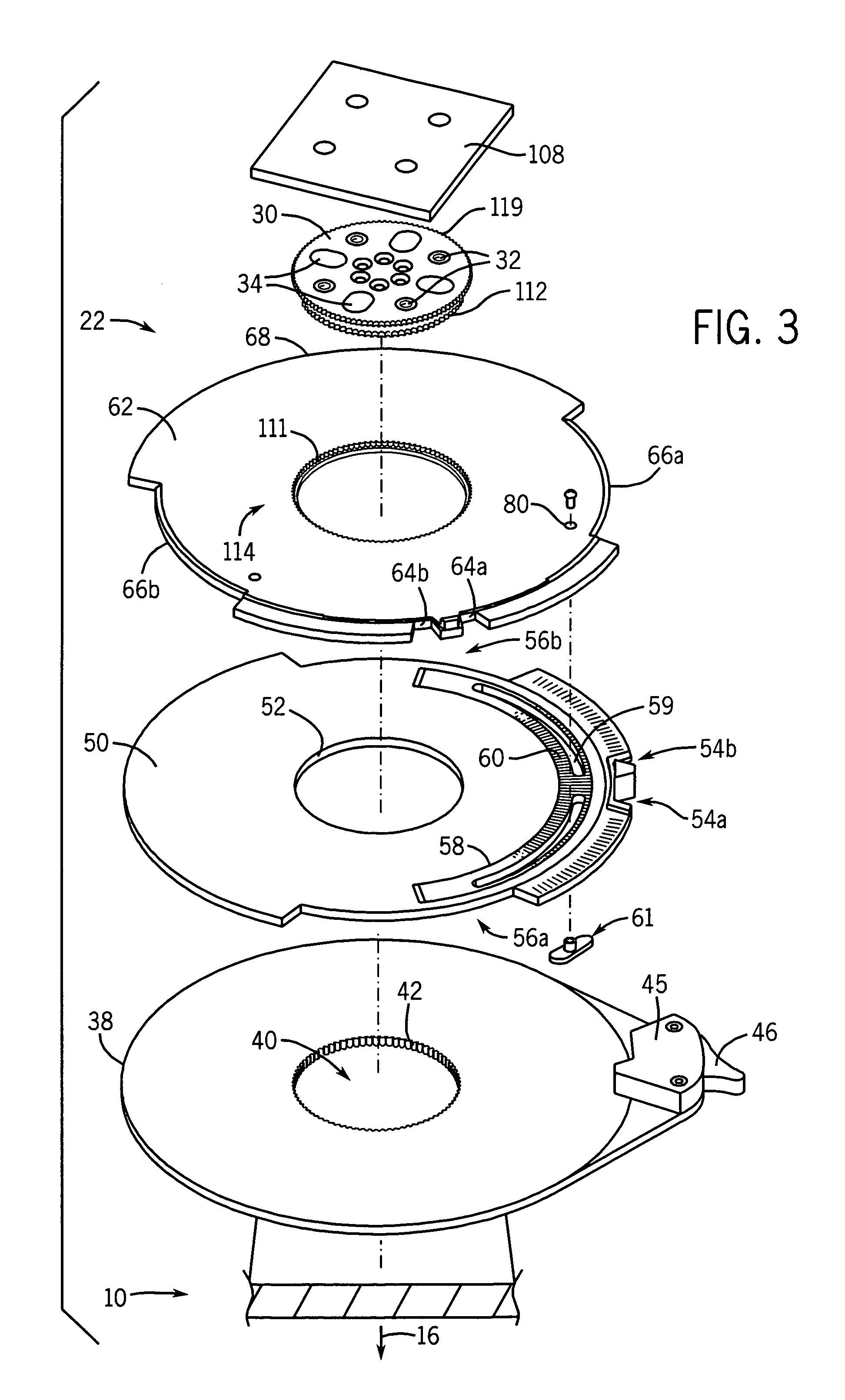
[0043]Referring now to FIG. 1, a snowboard 10 has a top surface 12 extending between a nose 14 of the snowboard 10 and a tail 16 where a direction of normal travel 18 of the snowboard is in the direction of the nose 14.

[0044]Two bindings 20 may be attached to the top surface 12, a first binding 20a attached to the binding rotational system 22 of the present invention to swivel between a skateboarding orientation 24 shown in solid lines along skateboarding angle 27, and a regular snowboarding orientation 26 shown in dotted lines along snowboarding angle 28. In the skateboarding orientation 24, the front of the foot faces the nose 14, while in the snowboarding configuration, the front of the foot extends along a snowboarding angle 28 extending generally along a transverse axis 29. The rear binding 20b extends along the transverse axis 29 at a fixed stance angle according to conventional technique.

[0045]Referring to FIG. 2, a snowboard 10 may also be used in so-called “goofy” mode in w...


PUM


Abstract

A snowboard boot binding rotation system provides for detent notches that may be adjusted in rotational separation by the relative rotation of two co-rotating disks. Adjustment of the location of the lock engaging these notches and adjustment in the separation between the notches allows complete adjustment of the user's stance for snowboarding and skateboarding. A pawl mechanism allows for a hard-lock and soft-lock to be used in the snowboarding stance and skateboarding stance, respectively, for convenience of use by not requiring the boot to be removed from the binding to make the stance angle adjustments.

Description

CROSS-REFERENCE TO RELATED APPLICATIONS[0001]This application claims the benefit of U.S. Provisional Application 60 / 620,947 filed Oct. 21, 2004 hereby incorporated by reference.STATEMENT REGARDING FEDERALLY SPONSORED RESEARCH OR DEVELOPMENT BACKGROUND OF THE INVENTION[0002]The invention relates generally to snowboard boot binding systems, and specifically to a binding system allowing the foot to be easily rotated between a snowboarding and skateboarding position preset to any of a variety of stance angles.[0003]Traditional skis are designed so that each foot of the skier, within its own boot, is firmly fastened to a ski oriented along the center line of the ski.[0004]Unlike skis, a snowboard is used by fastening both feet attached through boots fitting within boot bindings to a single board. The snowboard is ridden in a standing position facing sideways with the feet positioned transversely across the snowboard. One foot is fixed near the front of the board (nose) and the other fixe...

Claims


Application Information

Patent Timeline
Patent Type & Authority Patents(United States)
IPC IPC(8): A63C9/00
CPCA63C10/18A63C10/14
Inventor REYNOLDS, DWIGHT H.
Owner REYNOLDS DWIGHT H
Why Eureka
Try Eureka