Planar parallel robot mechanism with two translational degrees of freedom

a robot mechanism and translational degree technology, applied in the direction of mechanical control devices, process and machine control, instruments, etc., can solve the problems of lack of synchronization of movement and difficulty in meeting the requirements of precision of movement of the arm assembly, and achieve the effect of increasing the range of motion and being operated quickly and accurately

Inactive Publication Date: 2006-08-15
TIANJIN UNIV
View PDF1 Cites 21 Cited by
  • Summary
  • Abstract
  • Description
  • Claims
  • Application Information

AI Technical Summary

Benefits of technology

[0006]The present robotic mechanism overcomes the problems outlined above and advances the art by facilitating additional range of motion including at least two translational degrees of freedom in a mechanism that may be operated quickly and accurately.
[0009]The linkage having the location means may advantageously be provided with two spaced driven links mounted on common pivotal connections to the bell crank and platform respectively. It will be appreciated that the provision of twin driven links enhances the rigidity of the mechanism as a whole. Bracing means may be provided between the driven links. Such bracing means may comprise one or more members extending between the driven links. The members may extend substantially normal to the longitudinal direction of the links. Alternatively the members may extend diagonally between the links. The bracing means may preferably comprise a combination of both types of members.

Problems solved by technology

Conventional robotic arm assemblies have difficulty in meeting these requirements with precision of movement and may lack synchronicity of movement due to different drive mechanisms being in place to accomplish these goals.

Method used


Image

  • Planar parallel robot mechanism with two translational degrees of freedom
  • Planar parallel robot mechanism with two translational degrees of freedom
  • Planar parallel robot mechanism with two translational degrees of freedom

Examples


second embodiment

[0032]Referring now to FIGS. 7 and 8 there is shown a mechanism according to the present invention and generally designated 74. The mechanism 74 is for the most part similar to that described with reference to FIGS. 1 to 5 and hence common features are identified with like reference numerals. The mechanism 74 of FIGS. 7 and 8 differs from that of FIGS. 1 to 5 in that bracing means 76 are provided between the driven links 30, 32. The bracing means 76 include transverse brace members 78 (for example, brace members 78a, 78b and 78c as shown in FIG. 8) and diagonal brace members 80 (for example, brace members 80a, 80b, 80c and 80d as shown in FIG. 8). In the embodiment shown there are provided three transverse members 78 positioned respectively at each end and midway between the driven links 30, 32, and four diagonal members 80 provided in two pairs. It will be understood that other arrangements of the bracing members 78, 80 are possible. The inclusion of the bracing members 78, 80 has ...

third embodiment

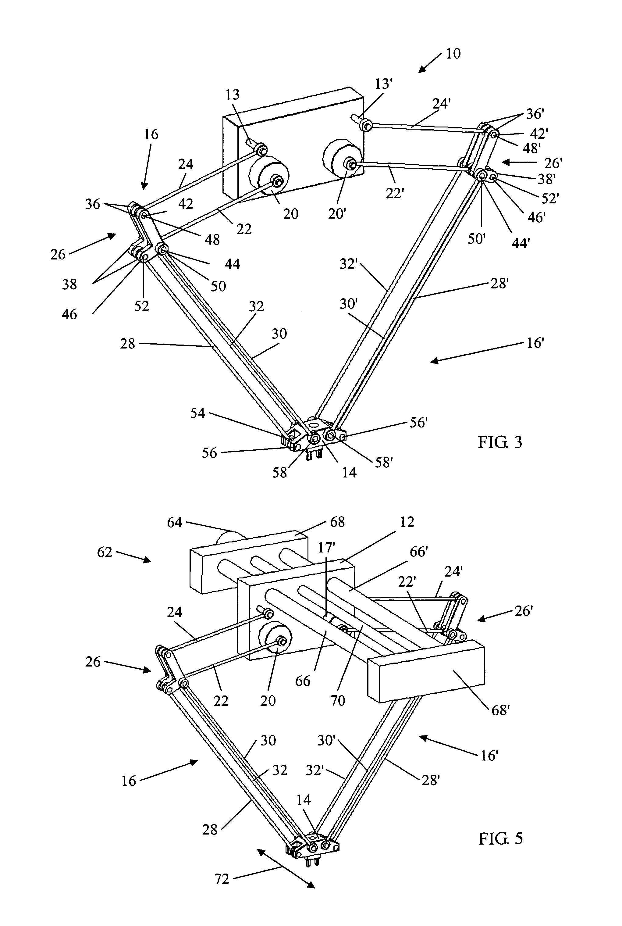
[0034]Referring finally to FIG. 6 there is shown a mechanism according to the present invention generally designated 82. As before, features common to the previously described embodiments are identified with like reference numerals. The mechanism 82 differs from those previously described in that it is provided on one side with a linkage arrangement 16 of the previously described type and on the other side with a simplified linkage arrangement 84. The simplified arrangement 84 comprises a drive link 86 fixed for rotation with a drive shaft 20 and a driven link 88 pivotally connected to the platform 14. The drive and driven links 86, 88 are joined by a common pinned link or hinge 90. It will be readily understood that the more complicated linkage arrangement 16 maintains the required orientation of the platform 12 relative to the base 12, while the simplified linkage arrangement 84 enables motive forces from the drive shaft 20 with which it is associated to be applied to the platform...


PUM


Abstract

A linkage mechanism for a pick and place robot includes two rotatable drive members mounted on a base and connected to a platform by a respective two element linkage. The mid point of the two element linkage has a bell crank, the arms of which are connected to first and second location links anchored respectively at the base and platform. The platform may be configured to carry various implements, and the mechanism permits movement thereof in two dimensions by selective motion of the drive members.

Description

BACKGROUND[0001]1. Field of the Invention[0002]The present invention relates to a translational parallel robot mechanism of the type typically referred to as a pick and place robot.[0003]2. Description of the Related Art[0004]Pick and place robot mechanisms are typically utilized in light industries, such as the electronics industry and packaging industries, where such robotic mechanisms are required for accurate repetitive performance of simple operations that occur many times over. Such an operation may, for example, involve the repeated picking up of items at a first location with a gripping mechanism, moving a gripped item to a second location, and releasing said item at the second location. The gripping mechanism is typically mounted to a movable platform.[0005]In order to meet performance criteria that are typically required of a robot mechanism of this type, one requirement may be that the platform is moved at a relatively high speed with two degrees of freedom in a movement ...

Claims


Application Information

Patent Timeline
Patent Type & Authority Patents(United States)
IPC IPC(8): B25J17/00B25J18/00B25J9/10B25J11/00
CPCB25J9/1065Y10T74/20329Y10T74/20305
Inventor HUANG, TIANLI, MENGLI, ZHANXIANCHETWYND, DEREK G.WHITEHOUSE, DAVID J.
Owner TIANJIN UNIV
Why Eureka
Try Eureka