Camera system

a technology of interchangeable lenses and cameras, applied in the field of lenses interchangeable camera systems, can solve the problems of not revealing the improvement in the accuracy of the focus information itself, and achieve the effects of reducing the time required to detect the focus position in reducing the frequency of communicating focus lens position information, and improving the accuracy of the contrast autofocus operation

Active Publication Date: 2013-08-27
PANASONIC CORP
View PDF38 Cites 5 Cited by
  • Summary
  • Abstract
  • Description
  • Claims
  • Application Information

AI Technical Summary

Benefits of technology

[0006]An object of the present embodiments is therefore to provide a lens-interchangeable camera system having improved accuracy of an autofocus operation in a contrast method.
[0008]According to a camera system having the above-described configuration, a position of the focus lens can be accurately obtained with the focus lens being moved, and thus fast and accurate contrast autofocus operation can be achieved.
[0010]By this configuration, communication can be stopped (ended) by both the camera body and the interchangeable lens. As a result, communication of position information of the focus lens can be performed at optimal timing and accordingly the accuracy of a contrast autofocus operation can be improved.
[0012]By this configuration, the lens controller avoids simultaneously obtaining a timing signal and a position information request signal. As a result, the lens controller can exclusively perform a lens position detection process, and the like, upon obtaining a timing signal and a lens position information transmission process upon obtaining a position information request signal.
[0014]By this configuration, the frequency of communicating focus lens position information can be reduced compared to the case in which the body controller requests the interchangeable lens for lens position information each time focus lens position information is stored in the storage unit. As a result, the time required to detect a focus position in a contrast autofocus operation can be reduced and accordingly the accuracy of a contrast autofocus operation can be improved.
[0015]According to the present embodiments, in a lens-interchangeable camera system, the accuracy of a contrast autofocus operation can be improved.

Problems solved by technology

It does not disclose an improvement in the accuracy of focus information itself that is obtained by the contrast method.

Method used


Image

  • Camera system
  • Camera system
  • Camera system

Examples


first embodiment

1-1. Configuration

[0029]1-1-1. Overview

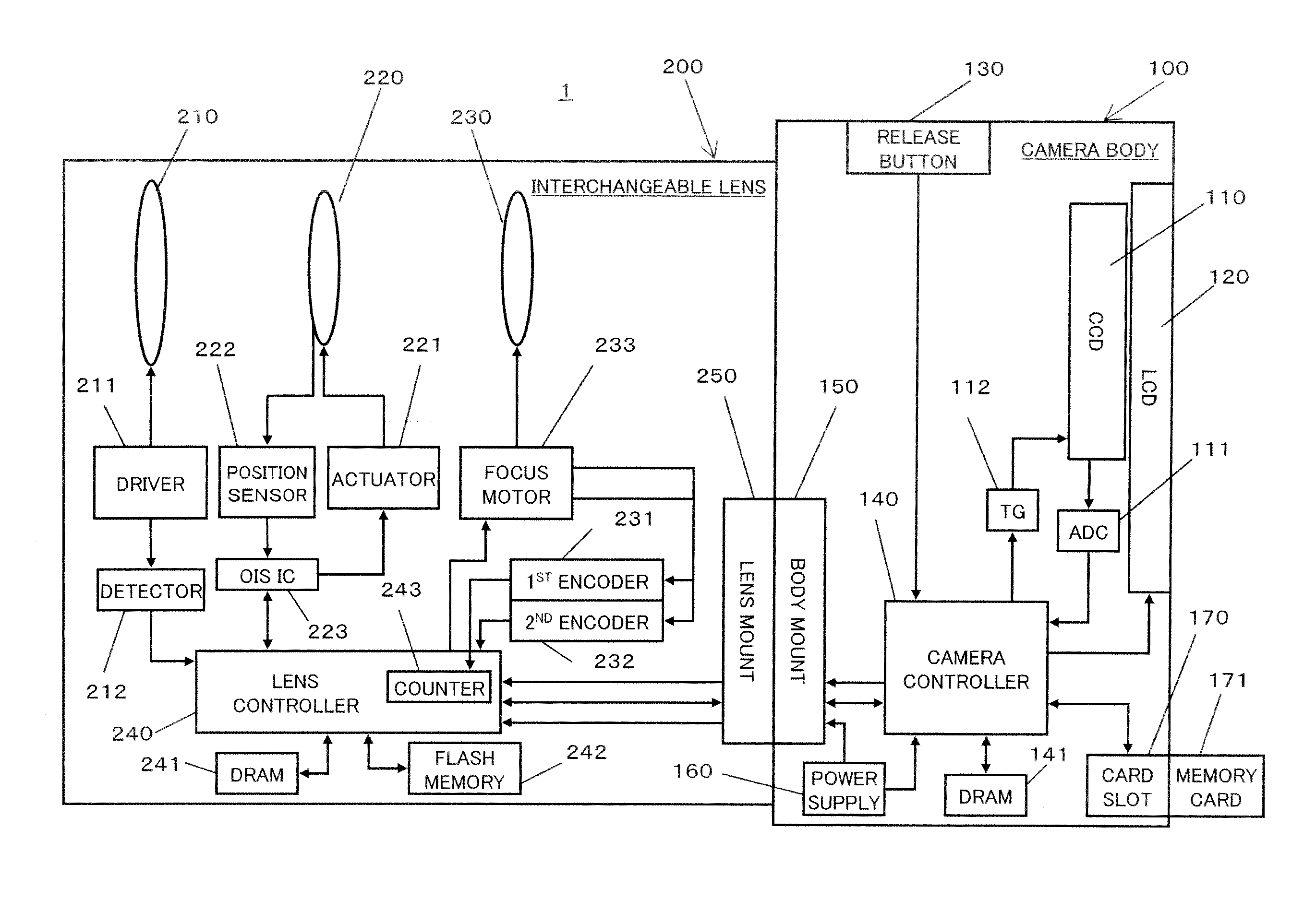
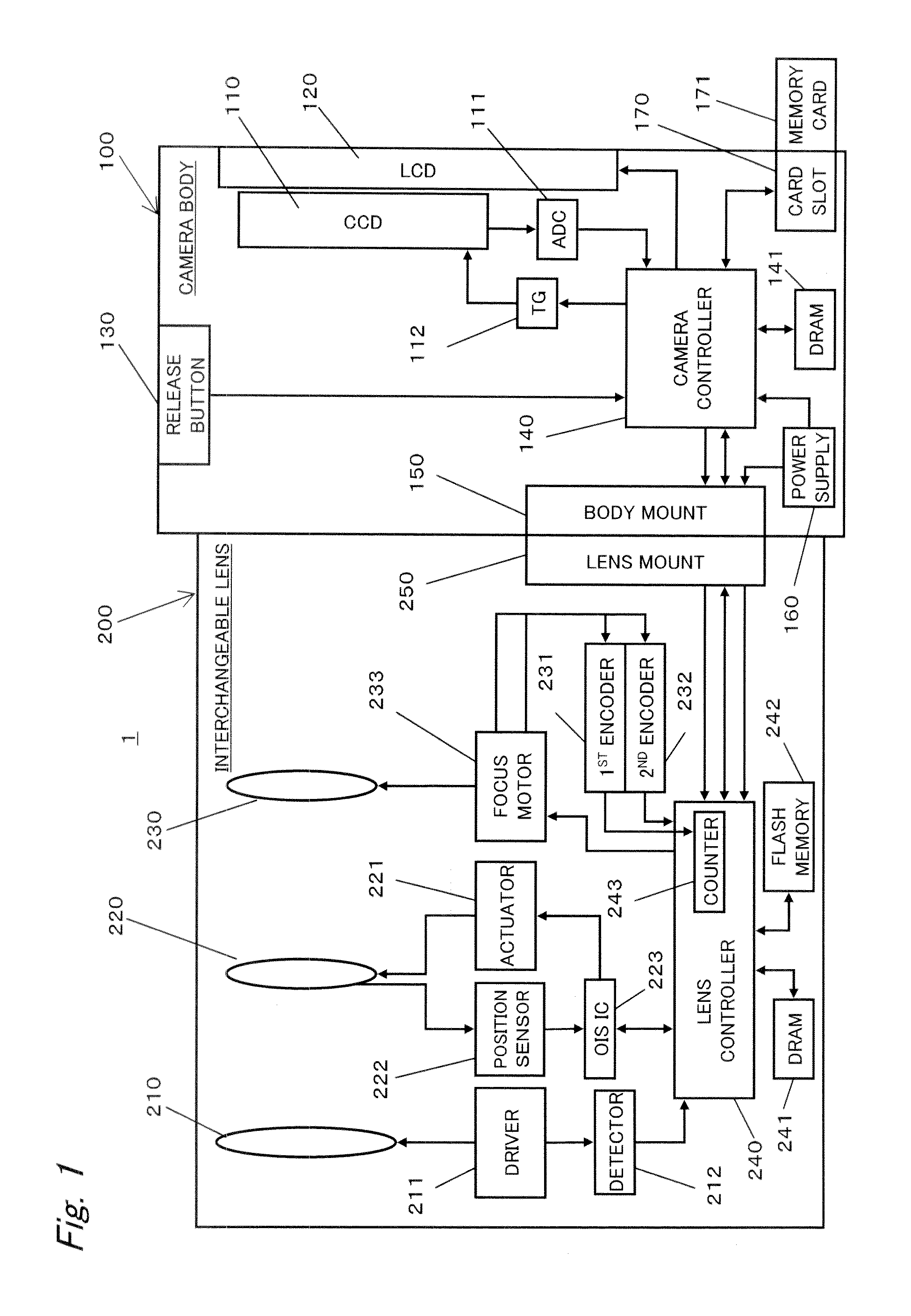
[0030]FIG. 1 is a block diagram showing a configuration of a camera system according to embodiments. A camera system 1 includes a camera body 100 and an interchangeable lens 200 mountable to the camera body 100. The camera system 1 can perform an autofocus operation in a contrast method, based on image data generated by a CCD image sensor 110.

[0031]1-1-2. Configuration of the Camera Body

[0032]The camera body 100 includes the CCD image sensor 110, a liquid crystal display (LCD) monitor 120, a camera controller 140, a body mount 150, a power supply 160, and a card slot 170.

[0033]The camera controller 140 controls the entire operation of the camera system 1 by controlling components such as the CCD image sensor 110 in response to an instruction from operation members such as a release button 130. The camera controller 140 transmits a vertical synchronizing signal to a timing generator 112. In parallel with this, the camera controller 140 generates...

second embodiment

[0094]The present embodiment describes another example of the contrast AF operation. The configuration and basic operation of the camera system 1 are the same as those in the first embodiment.

[0095]FIG. 6 is a flowchart of a contrast AF operation according to the present embodiment. Steps S201 to S205 and steps S211 to S214 are respectively the same as steps S101 to S105 and steps S107 to S110 in the flowchart of FIG. 5 according to the first embodiment.

[0096]An exposure synchronizing signal is transmitted from a camera controller 140 to a lens controller 240, and position information of a focus lens 230 is stored in a DRAM 241 by the lens controller 240. An AF evaluation value of image data obtained from a CCD image sensor 110 is calculated by the camera controller 140 (S201 to S205). Then, the camera controller 140 determines whether the CCD image sensor 110 has completed exposure for a predetermined number of frames (S206). In the present embodiment, the predetermined number is t...

third embodiment

[0112]In the second embodiment, in order to prevent a collision between an exposure synchronizing signal and a position information request command, a predetermined prohibition period is provided after the transmission of a position information request command and during the prohibition period the transmission of an exposure synchronizing signal is prohibited (stopped). The present embodiment describes an example in which in order to prevent a collision between an exposure synchronizing signal and a position information request command, the transmission timing of a position information request command is shifted so that the transmission of an exposure synchronizing signal does not take place during a prohibition period. The configuration and basic operation of the camera system 1 are the same as those in the first embodiment.

[0113]FIG. 9 is a flowchart of a contrast AF operation according to the present embodiment. Steps S301 to S305 and steps S309 to S312 are respectively the same ...


PUM


Abstract

In a camera system including an interchangeable lens and a camera body, a body controller performs control a drive signal transmission unit to drive a focus lens in a predetermined direction, and transmit a timing signal to the interchangeable lens. The lens controller performs control to detect a position of the focus lens in synchronization with the timing signal received from the camera body and store the detected position in a storage unit.

Description

BACKGROUND[0001]1. Technical Field[0002]The technical field relates to a lens-interchangeable camera system, and more particularly to a camera system capable of performing an autofocus operation in a contrast detection method.[0003]2. Related Art[0004]JP-A-2003-295047 discloses autofocus control that employs both a phase-difference detection method and a contrast method. An imaging apparatus disclosed in JP-A-2003-295047 corrects focus control information obtained by the phase-difference detection method, based on focus information obtained by the contrast method. Specifically, correction information for compensating for insufficient detection accuracy of the phase-difference detection which has excellent high-speed performance is obtained based on information indicating a focus status obtained by using contrast detection which enables focus determination at high accuracy. This arrangement can provide focus control by the phase-difference detection method with higher speed and highe...

Claims


Application Information

Patent Timeline
Patent Type & Authority Patents(United States)
IPC IPC(8): G03B13/36
CPCG03B13/36H04N5/23212H04N5/23209H04N23/663H04N23/673
Inventor SHIBUNO, KOJITAKAHATA, JUNJIOKAMOTO, MITSUYOSHIKITAHIRA, NAOTAKE
Owner PANASONIC CORP
Why Eureka
Try Eureka