Driver module, electronic device, method of controlling driving module

A driving module and driving device technology, which is applied in the direction of mechanical equipment, branch equipment, color TV parts, etc., can solve the problems of increased scanning interval, increased number of steps, deviation of lens frame movement range, etc., to ensure self-focusing Effects of accuracy, deviation suppression, and high self-focus accuracy

Inactive Publication Date: 2012-03-21
SEIKO INSTR INC
View PDF2 Cites 0 Cited by
  • Summary
  • Abstract
  • Description
  • Claims
  • Application Information

AI Technical Summary

Problems solved by technology

[0018] As described above, if there are individual differences in the amount of deformation of the shape memory alloy wire with respect to the command value, when the resistance of the shape memory alloy wire is changed step by step with a certain range, there will be deviations in the movement range of the lens frame, and the automatic The problem of focus accuracy
For example, a shape memory alloy wire with a large amount of deformation may increase the scanning interval and may not ensure the accuracy of self-focusing
On the other hand, the shape-memory alloy wire with a small amount of deformation may increase the number of steps required for the necessary movement amount, and the time until the completion of self-focusing may become longer.

Method used


Image

  • Driver module, electronic device, method of controlling driving module
  • Driver module, electronic device, method of controlling driving module
  • Driver module, electronic device, method of controlling driving module

Examples


Embodiment Construction

[0055] Hereinafter, embodiments of the drive module, the electronic device, and the control method of the drive module according to the present invention will be described based on the drawings.

[0056] In addition, in some drawings, for ease of observation, for example, the Figure 5 The shown lens unit 12 and other components are shown in the figure.

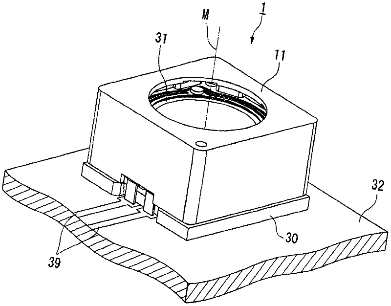
[0057] In addition, the symbol M in the figure is the same as Figure 5 The virtual axis line of the driving module 1 where the optical axis of the shown lens 50 coincides shows the driving direction of the lens frame 4 described later. Hereinafter, in order to simplify the description, in the description of each disassembled component, the position or direction may be referred to based on the positional relationship with the axis M at the time of assembly. For example, even when there is no clear circle or cylindrical surface among the components, the direction along the axis M may be simply referred to as the "axis direct...


PUM


Abstract

The driving module controls the supply of current to a shape memory alloy member by setting a command value for an electrical resistance of the shape memory alloy member so that the lens frame is moved intermittently to thereby controlling the driving of driving means. The driving module includes control means which includes resistance detection means, command value generation means, and current supplying means. The command value generation means changes the command value gradually by a predetermined variation width R so that the electrical resistance of the shape memory alloy member increases or decreases gradually by a predetermined width when the lens frame is moved intermittently. Moreover, the command value generation means performs a correction calculation which uses the ratio of an actual reference value R 0 of the electrical resistance of the shape memory alloy member to an ideal reference value R stan of the electrical resistance of the shape memory alloy member as a correction ratio to calculate a correction variation width by multiplying the correction ratio by an ideal variation width R step of the command value R t ( n ) to thereby change the command value R t ( n ) gradually using the correction variation width as the variation width R.

Description

technical field [0001] The present invention relates to a driving module, an electronic device and a control method of the driving module for driving a lens frame holding a lens to perform self-focusing for automatic focusing. Background technique [0002] In an imaging device having a lens such as a camera, when taking pictures, such as Figure 13 As shown, it is necessary to perform an operation to move the lens to a position (focus point) where the harmonic component of the image becomes a peak value, and a large number of imaging devices having an autofocus function that automatically performs this operation (focus) are provided. [0003] As a driving module for realizing the above-mentioned self-focusing, conventionally, a driving module for driving a lens frame by utilizing deformation properties of a shape memory alloy accompanied by a temperature change, as described in Patent Document 1 below, for example, has been proposed. The driving module includes: a supporting...

Claims


Application Information

Patent Timeline
Patent Type & Authority Applications(China)
IPC IPC(8): G02B7/04H04N5/225
CPCH04M1/0264G03B17/02F03G7/065G02B7/04F03G7/0614
Inventor 野边哲也枪田光男
Owner SEIKO INSTR INC
Why Eureka
Try Eureka