Vehicle mounted electrical outlet box

a technology for electrical outlets and vehicles, applied in the direction of coupling device details, electrical discharge lamps, coupling device connections, etc., can solve the problems of detecting switch operation erroneously, detecting switch operation with incomplete reliability, and outlet box size increase, so as to promote stable operation of detection function and improve reliability. , the effect of compact siz

Inactive Publication Date: 2006-08-15
MATSUSHITA ELECTRIC WORKS LTD
View PDF10 Cites 12 Cited by
  • Summary
  • Abstract
  • Description
  • Claims
  • Application Information

AI Technical Summary

Benefits of technology

[0006]Taking at least the above-noted shortcomings into consideration, the present invention provides a more compact vehicle mounted electrical outlet box that incorporates a reliable plug blade detecting device.
[0010]As noted previously, the vehicle-mounted electrical outlet box invention can be made to more compact dimensions due to the detection mechanisms being located between the two blade receivers which contact the plug blades. Furthermore, the contact points that operate according to the insertion of each plug blade are electrically wired in series so as to activate the detection function only when both plug blades have been inserted. This construction provides a device and method of preventing the insertion of one plug blade, which may result from mischief of other factors, from activating the detection function, and promotes stable operation of the detection function to improve reliability.

Problems solved by technology

Conventional vehicle-mounted electrical outlet boxes of the type noted above require that a plug blade detecting switch be mounted external to the outlet box, thus increasing the size of the outlet box and detracting from its external appearance.
Further, the detecting switch does not operate with complete reliability as it may activate the blade detection switch to an “on” state even though the blades may not have been inserted into the outlet.
Also, the detecting switch may operate erroneously as a result of vibration or the plug being inserted at an inclined orientation.

Method used


Image

  • Vehicle mounted electrical outlet box
  • Vehicle mounted electrical outlet box
  • Vehicle mounted electrical outlet box

Examples


Embodiment Construction

[0067]The particulars shown herein are by way of example and for purposes of illustrative discussion of the embodiments of the present invention only and are presented in the cause of providing what is believed to be the most useful and readily understood description of the principles and conceptual aspects of the present invention. In this regard, no attempt is made to show structural details of the present invention in more detail than is necessary for the fundamental understanding of the present invention, the description is taken with the drawings making apparent to those skilled in the art how the forms of the present invention may be embodied in practice.

[0068]The following will describe embodiments of the invention with reference to the drawings.

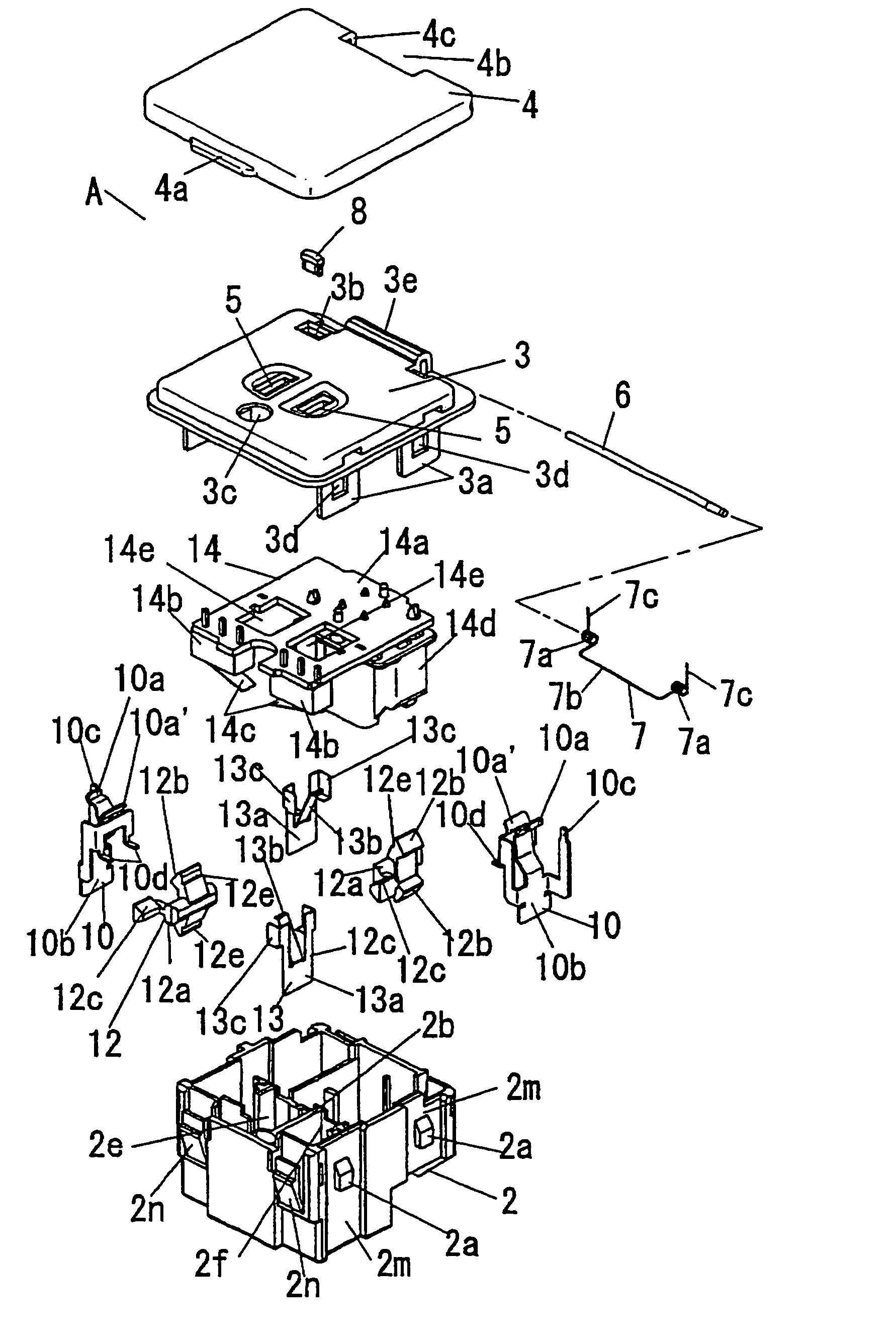
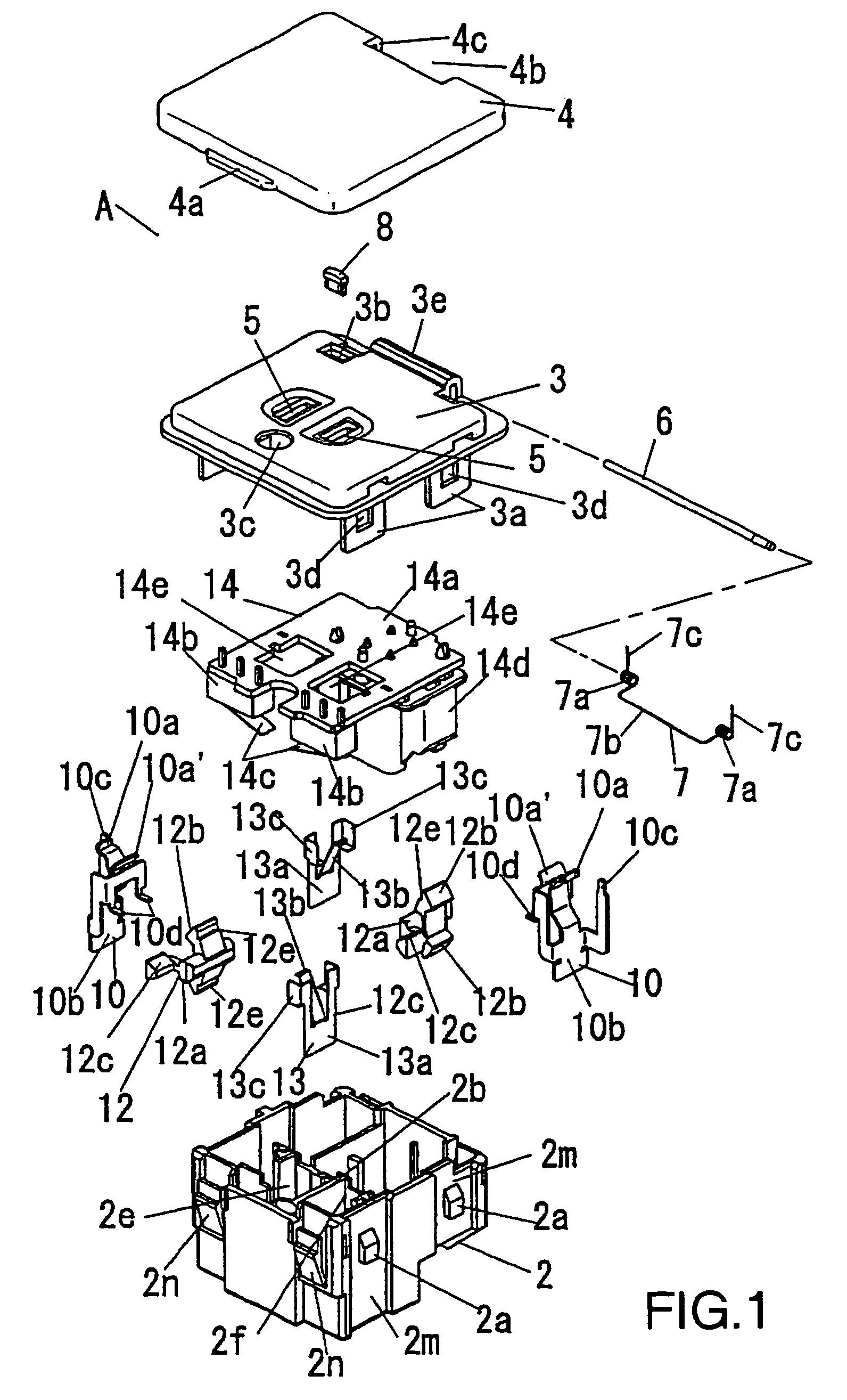
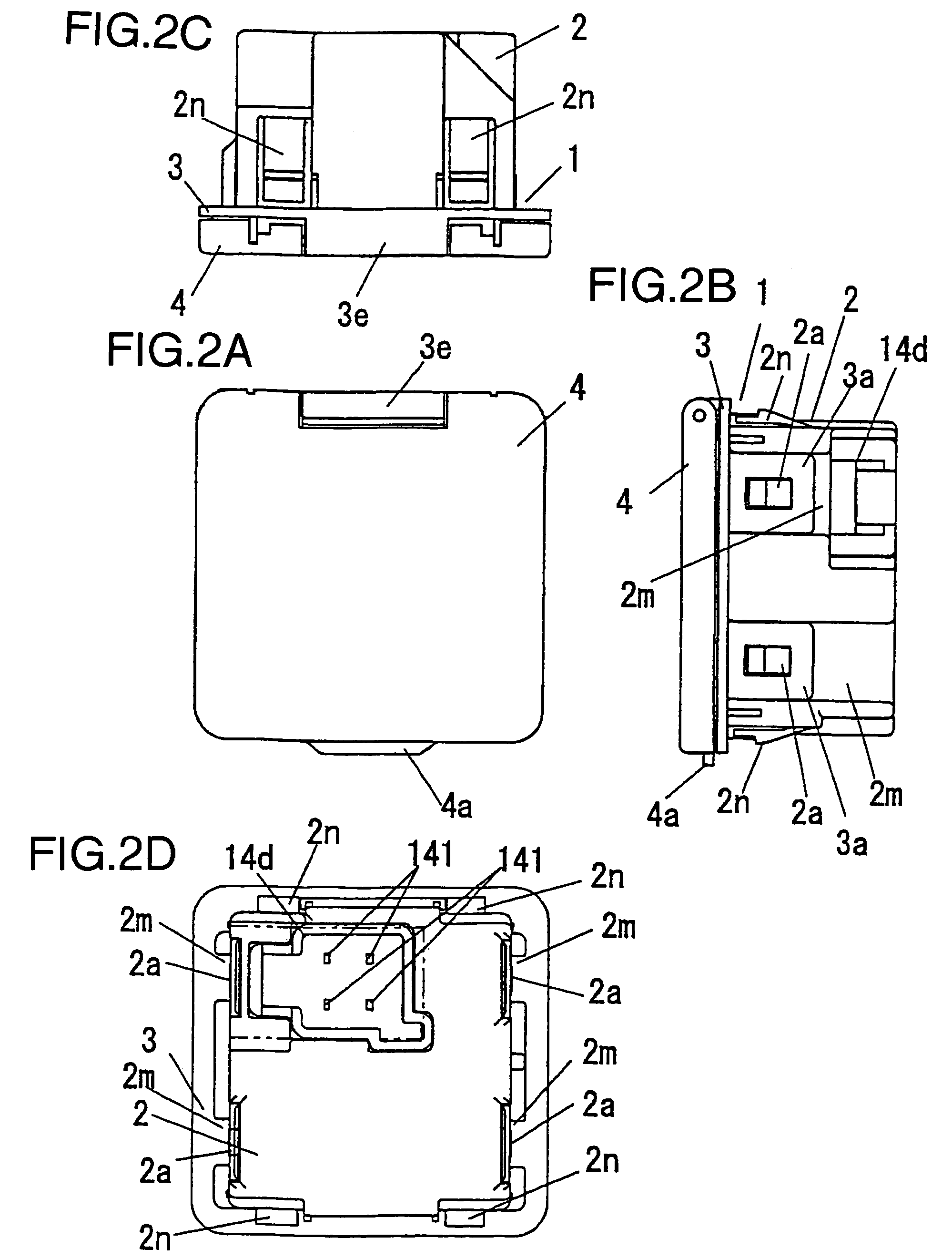
[0069]As illustrated in FIGS. 1 through 3, the electrical outlet box of the present invention includes case 1 which is formed from the joining of body 2 and cover 3, and external cover 4 which pivots on one edge of case 1 to positions...


PUM


Abstract

A compact vehicle-mounted electrical outlet box offering a reliable plug blade detection function. The electrical outlet box is formed from synthetic resin rectangular case 1 which includes body 2 and cover 3. A pair of electrical plug blades 100 and 101 are inserted into plug blade insertion slots 5 located on the front surface of case 1 through which the plug blades contact two blade receiver parts 10. The forceful contact of plug blades 100 and 101 rotate two pivot levers 12 which convert the insertion force of plug blades 100 and 101 to a directional force. Two return springs 13 apply pressure to pivot levers 12 in a direction opposite to that applied by the insertion of plug blades 100 and 101. Printed circuit block 14, which is comprised of circuit base plate 14a to which each microswitch 14b is installed, is housed within case 1. The two pivot levers 12 are located at the approximate mid-point of body 2 between the two mutually facing blade receiver parts.

Description

BACKGROUND OF THE INVENTION[0001]1. Field of the Invention[0002]The invention relates to a vehicle mounted electrical outlet box incorporating a switch that detects the presence of plugged in terminal blades.[0003]2. Description of the Background Information[0004]Automotive vehicles have recently being equipped with onboard electrical outlet boxes that allow the use of electrical appliances in the vehicle. These vehicle mounted electrical outlet boxes are able to detect the presence of plug in terminal blades that have been inserted to the outlet. Japanese Kokai (laid open) Patent No. 2000-301991, and particularly paragraphs 0016–0022,0030 and 0031; and FIGS. 1–5, show a conventional automotive electrical outlet box.[0005]Conventional vehicle-mounted electrical outlet boxes of the type noted above require that a plug blade detecting switch be mounted external to the outlet box, thus increasing the size of the outlet box and detracting from its external appearance. Further, the detec...

Claims


Application Information

Patent Timeline
Patent Type & Authority Patents(United States)
IPC IPC(8): H01R29/00H01R13/703H01R13/193H01R13/447H01R13/52H01R24/76
CPCH01R13/193H01R2201/26H01R13/447
Inventor MATSUKAWA, KAZUSHIYOSHIDA, MASARUKITAMURA, MASUO
Owner MATSUSHITA ELECTRIC WORKS LTD
Why Eureka
Try Eureka