Linear object identification tag, and installation instrument and installation method for same, linear object with connector

a technology of object identification and identification tag, which is applied in the direction of identification means, cables, insulated conductors, etc., can solve the problems of increasing production costs, reducing working efficiency, and increasing the cost of identification tags, so as to achieve the effect of greatly improving operation efficiency and accurately managing the status of the connection

Inactive Publication Date: 2006-08-15
NTT ADVANCED TECH
View PDF11 Cites 128 Cited by
  • Summary
  • Abstract
  • Description
  • Claims
  • Application Information

AI Technical Summary

Benefits of technology

[0030]Therefore, installation is possible by simply inserting the linear object from an aperture part, and the efficiency of the installation operation can be greatly improved. Furthermore, because the shape and dimensions of the linear object are not especially restricted provided that it can be fitted inside the linear object identification tag, it is applicable to various types of linear object of different shapes and dimension, and as there is no cumbersome task such as preparing many types of linear object identification tags to suit the linear objects, and selecting a linear object identification tag to suit a linear object during the installation, there is the advantage that the installation operation can be made more efficient.
[0051]When these ancillary data are displayed on the hand held device, the operator instantly becomes aware of a lot of information and is able to carry out the operation and make decisions, so that the advantages of mistake reduction in the operation, and improved efficiency of operation can be achieved.

Problems solved by technology

As a result, the shape and dimensions of the grooves 200 require high accuracy, and there is a concern of increasing production cost.
As a result, the cost of the identification tags becomes relatively high, and working efficiency decreases as the installation operation has to be carried out while selecting identification tags.
Also, when installing on a number of linear objects arranged with high density in a narrow space, because handling the identification tags and determining the positioning of the grooves and the linear objects become difficult, installation workability becomes reduced even further.
If each of the clip parts is forced together while the linear object is dislocated from the grooves 200, then the linear object will be pressed by the part outside the grooves, and there is a possibility of causing a defect in one or both of the linear object and the identification tag.
However, this margin is generally given to be only slightly larger than the dimension of the groove and linear object, and is only able for example to absorb the dimensional change due to temperature change.
Therefore, the possibility of installation of a single identification tag on linear objects with differing shape and dimensions is not achieved, and the inefficient operation of installing while selecting the identification tag is still involved.
Also, because there is still an operation of fitting the linear object in the groove while opening the clip parts, and closing and pressing together the clip parts while paying careful attention not to have the linear object parted from the groove, problems such as the reduction of operation workability, the linear object being pressed by parts other than the grooves, or the operation of installation onto a linear object with flexure tendency being difficult, still cannot be solved.
Therefore, especially when having a number of linear objects provided (at high density) in a narrow space, there are concerns such as that the workability of the installation of a linear object identification tag is reduced due to the restrictions on the movement of hands and fingers, that the identification tag may be dropped, and that the linear object may become defective while fumbling with linear objects during the installation.
That is to say, the conventional connector interconnection status management led easily to incorrect management information due to the records on the labels being handwritten by the operator, connector receptacle selection being carried out by means of visual checking, and records of connection presence status of the connector receptacle being hand written.
In addition it had the disadvantage of the possibility of communication failure and so forth caused by incorrectly removing a connector in communication due to this incorrect information.
Therefore, there is the disadvantage that operation efficiency becomes drastically reduced as communication lines get damaged due to entanglements between labels, or between labels and communication lines, during the operation of connection and removal of the communication lines with connectors.
Furthermore, there is the major disadvantage that this leads to serious failures such as removal of the incorrect communication line with connectors, or connection to an incorrect connector receptacle due to erroneous visual recognition of a label.
However, as connector receptacles are interconnected to the connector receptacle board in high density, the density of communication lines with connectors 66 extending from the connector receptacle becomes higher, and the operation of removal and connection of connectors provided in the inmost recesses of dense connector communication lines has become difficult to carry out by hand.
As just described, not only is the operation cumbersome and of reduced workability, but the communication line with connectors, and the connector receptacle, which are the objects of the operation, need to be kept or verified at all times while two types of hand held instruments are exchanged, and if care is not taken, the incorrect communication line with connectors will be removed and there is a risk of communication failure occurring.
Therefore, the risk of entering incorrect information at this stage remains.

Method used


Image

  • Linear object identification tag, and installation instrument and installation method for same, linear object with connector
  • Linear object identification tag, and installation instrument and installation method for same, linear object with connector
  • Linear object identification tag, and installation instrument and installation method for same, linear object with connector

Examples


first embodiment

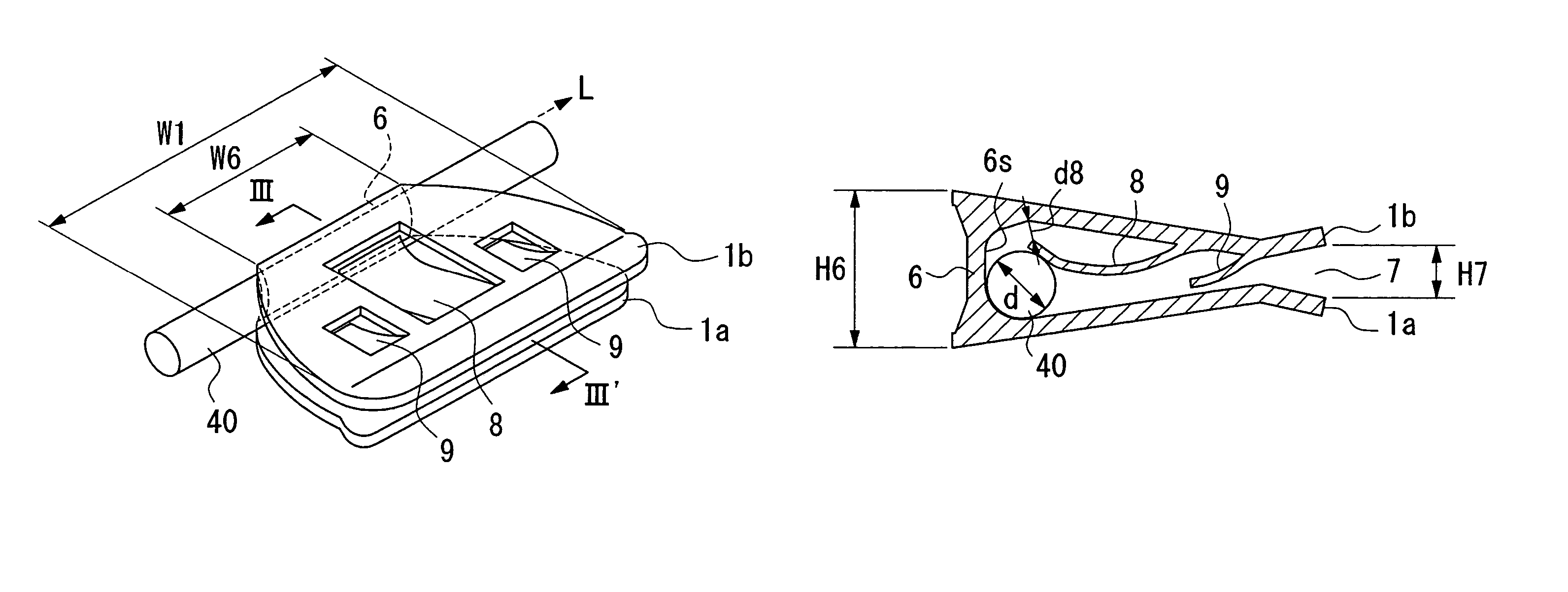
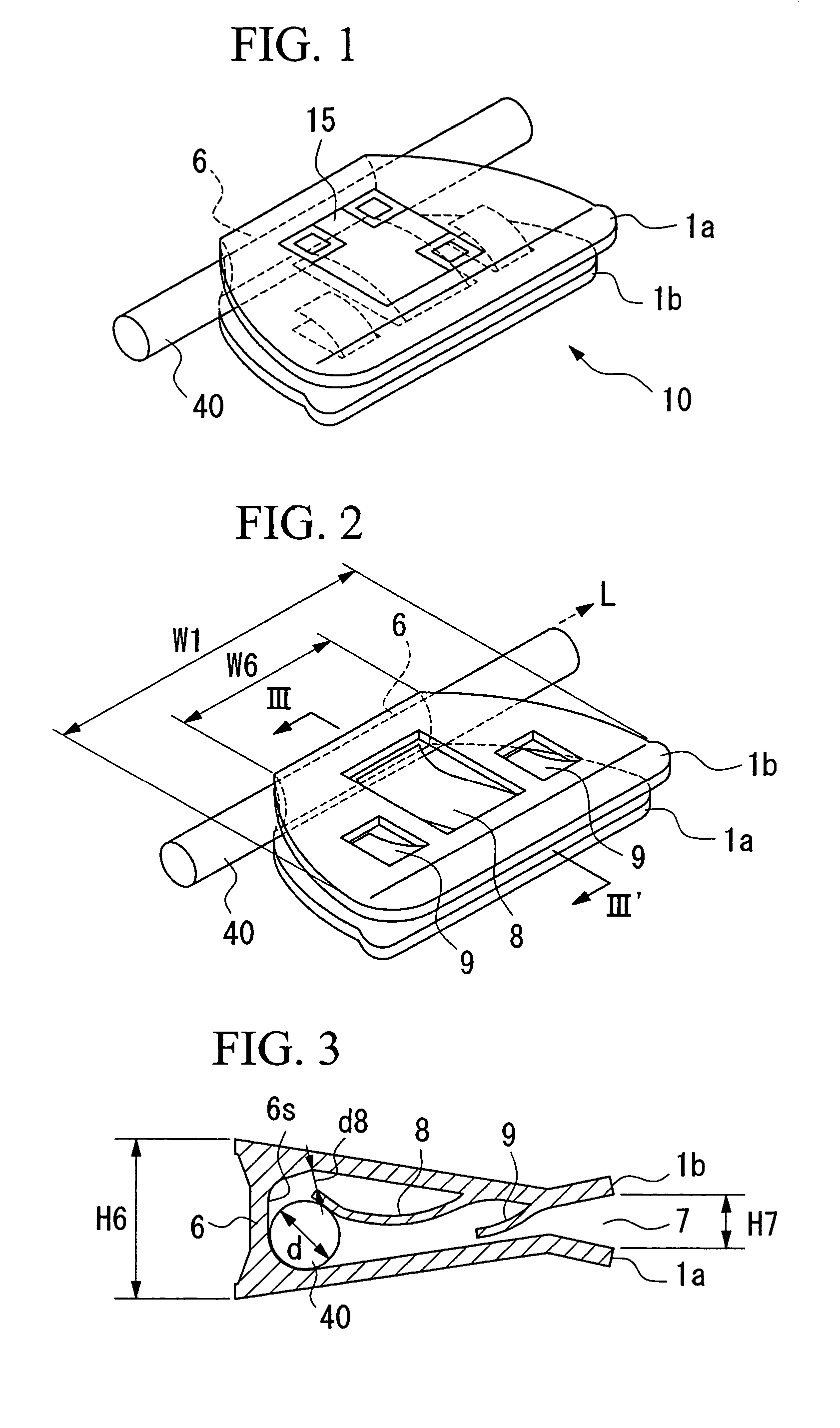
[0091]FIG. 1 to FIG. 3 are diagrams showing the construction of a linear object identification tag according to the present invention. In FIG. 1, the linear object identification tag 10 has a cross section U shape, and has one edge of each tabular clip part 1a and 1b openably joined at a base part 6. A linear object 40 is housed and installed inside the identification tag. An outer face of one clip part 1a has an identification denotation 15 provided to identify and manage the linear object. This identification denotation may be a digit, letter, marking, color, barcode or two-dimensional code. Furthermore, the identification denotation may be directly marked on the outer face of the clip part by means of printing, laser and so forth, and also, the label may be attached on the outer face of the clip part after the identification denotation has been printed on it. Identification denotations may be formed on both clip parts if possible.

[0092]FIG. 2 shows the appearance of the linear ob...

second embodiment

[0154]FIG. 25 shows the connector interconnection instrument 722. In this embodiment, a stress detecting sensor 726, which detects the variation and direction of axial mechanical stress of the shaft 722c, is provided in the middle of the shaft 722c. The stress detecting 726 determines the direction and variation of the stress applied in the axial direction of the connector interconnection 722, detects connecting and disconnecting operations, and retrieves the connector connection presence information. According to this method, a distinction between connection and disconnection can be accurately detected from the direction of the stress.

[0155]Also, not only the mechanical variation described above, but also electrical variation such as electrostatic capacity or electromagnetic field when the connector 75 is connected or disconnected to or from the connector receptacle 72, or optical variation such as of reflection light, may be detected by various types of sensor, and the connector c...


PUM


Abstract

The linear object identification tag 10 can be attached to and detached from a linear object 40. This tag has a clip body having a pair of clip parts 1a, 1b openably joined to a base part 6, and a holding part 8, 9 which holds the linear object 40 inside the linear object identification tag and is formed on an inner face of at least one of the clip parts 1a, 1b. Installation is thus efficiently performed by simply inserting the linear object 40 through an aperture part. 7. An installation tool (FIGS. 12, 13) with guide parts (22c, 22d) for opening the clip parts (1a, 1b) as they are slid along the tool is disclosed. In another embodiment, labels (719, 720) may be applied to plugs (75) and receptacle (72) and an instrument (722) with optical readers (723, 724) used to read codes on the labels.

Description

TECHNICAL FIELD[0001]The present invention relates to a linear object identification tag for individual management and identification of linear objects such as cords, wires and tubes, and an installation instrument and installation method for the same, and is suitable especially for the installation of linear objects positioned at high-density in a narrow space.[0002]Also, the present invention relates to a method for connector interconnection management for the central management of the connection status of connectors, and a connector, a connector receptacle, a connector receptacle board and a connector interconnection instrument which are used for the same.BACKGROUND ART[0003]Conventionally, an identification tag such as that shown in FIG. 28 and FIG. 29 for the individual management and identification of a linear object such as a cord or a wire, has been known.[0004]In FIG. 28, the identification tag has plate-like clip parts 100a and 100b with one of their edges joined so that t...

Claims


Application Information

Patent Timeline
Patent Type & Authority Patents(United States)
IPC IPC(8): G09F3/00H01R3/00F16B2/20G09F3/20
CPCF16B2/20G09F3/205G09F3/20G09F3/02H01R43/26H02G1/06
Inventor KUKITA, SHIGEZOHANARI, KENICHI
Owner NTT ADVANCED TECH
Why Eureka
Try Eureka