InGaAs image intensifier camera

a technology of image intensification and camera system, which is applied in can solve the problems that the field of imaging systems has continued to increase, and achieve the effect of compactness and effective

Inactive Publication Date: 2006-08-15
L3 TECH INC
View PDF31 Cites 8 Cited by
  • Summary
  • Abstract
  • Description
  • Claims
  • Application Information

AI Technical Summary

Benefits of technology

[0011]Embodiments of the invention may provide numerous technical advantages. A technical advantage of one embodiment is that an InGaAs camera can be synchronized to an internal or ex

Problems solved by technology

While known approaches have provided improvements over prior approaches, the challenges in the field of imagin

Method used


Image

  • InGaAs image intensifier camera
  • InGaAs image intensifier camera
  • InGaAs image intensifier camera

Examples


Embodiment Construction

[0018]So that the manner in which the above recited features, advantages, and objects of the present invention are attained can be understood in detail, more particular description of the invention, briefly summarized above, may be had by reference to the embodiment thereof that is illustrated in the appended drawings. In all the drawings, identical numbers represent the same elements.

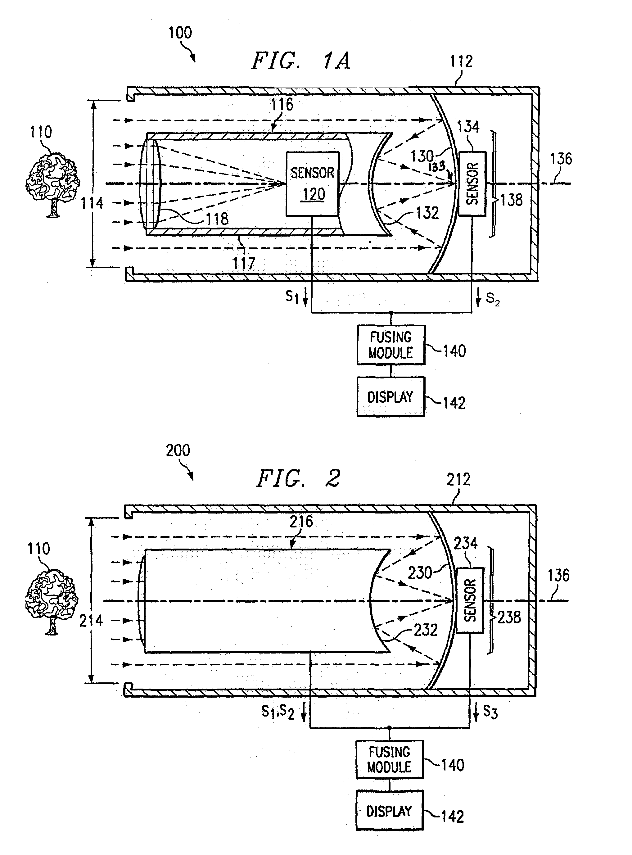
[0019]FIG. 1A illustrates a side view of one embodiment of a system 100 for gathering image data. System 100 receives light or an energy signal reflected from an object 110 and gathers information from the light or input signal to generate an image of object 110 on a display 142. System 100 may include an outer casing 112 having an aperture 114 through which light enters. Outer casing 112 may have any suitable shape such as a cylinder having a diameter in the range of 8–12 cm, for example, approximately 10 cm, and a length in the range of 12–15 cm, for example, approximately 14 cm. System 100 may also ...


PUM


Abstract

An InGaAs Image Intensifier (“I2”) Camera (C) detects and forms an image (310) to be viewed. An InGaAs photocathode Image Intensifier (312) is used to pass an amplified signal (316) from a screen (320). The InGaAs image intensification tube (312) is optically coupled (328) to an imaging device (322) for passing output light. The output light (316) from the InGaAs tube (312) is transformed by an electronic circuit (322) producing a desired signal output (324). The signal output (324) from the electronic circuit (322) may be further enhanced into an enhanced signal output (310). The enhanced signal output may be formatted into a form for viewing or may be saved.

Description

CROSS REFERENCE TO RELATED APPLICATIONS[0001]This application claims the benefit of U.S. Provisional Application Ser. No. 60 / 319,314, filed Jun. 12, 2002, entitled INGAAS IMAGE INTENSIFICATION CAMERA.BACKGROUND OF INVENTION[0002]1. Technical Field[0003]This invention relates generally to the field of imaging systems and more specifically to an InGaAs image intensification camera system.[0004]2. Background Art[0005]Multiple sensor imaging systems generate an image of an object by fusing data that is collected using multiple sensors. Gathering image data using multiple sensors, however, has posed challenges. In some systems, the sensors detect light received from separate apertures. Data generated from light from separate apertures, however, describe different points of view of an object that need to be reconciled in order to fuse the data into a single image. Additionally, using separate apertures for different sensors may increase the bulk of an imaging system.[0006]In other systems...

Claims


Application Information

Patent Timeline
IPC IPC(8): H04N5/225H01L27/146H01J31/50H01L31/00H04N5/235H04N5/265H04N5/355H04N5/369
CPCH04N5/2251H04N5/332H04N5/265H04N5/238H04N23/55H04N23/63H04N23/75H04N23/11
Inventor BACARELLA, ANTONIO V.OSTROMEK, TIMOTHY E.HOGAN, TIMOTHY B.DOSTER, RODNEY L.SHORT, JEFFREY C.ESTRERA, JOSEPH P.
Owner L3 TECH INC
Why Eureka
Try Eureka