Systems for deep resistivity while drilling for proactive geosteering

Active Publication Date: 2006-08-22
SCHLUMBERGER TECH CORP
View PDF12 Cites 85 Cited by
  • Summary
  • Abstract
  • Description
  • Claims
  • Application Information

AI Technical Summary

Problems solved by technology

For example, a poorly placed well may have a much lower productivity than if the well had been drilled in a better location.
However, seismic surveys are incapable of providing the desired resolution and accuracy to acc

Method used


Image

  • Systems for deep resistivity while drilling for proactive geosteering
  • Systems for deep resistivity while drilling for proactive geosteering
  • Systems for deep resistivity while drilling for proactive geosteering

Examples


Embodiment Construction

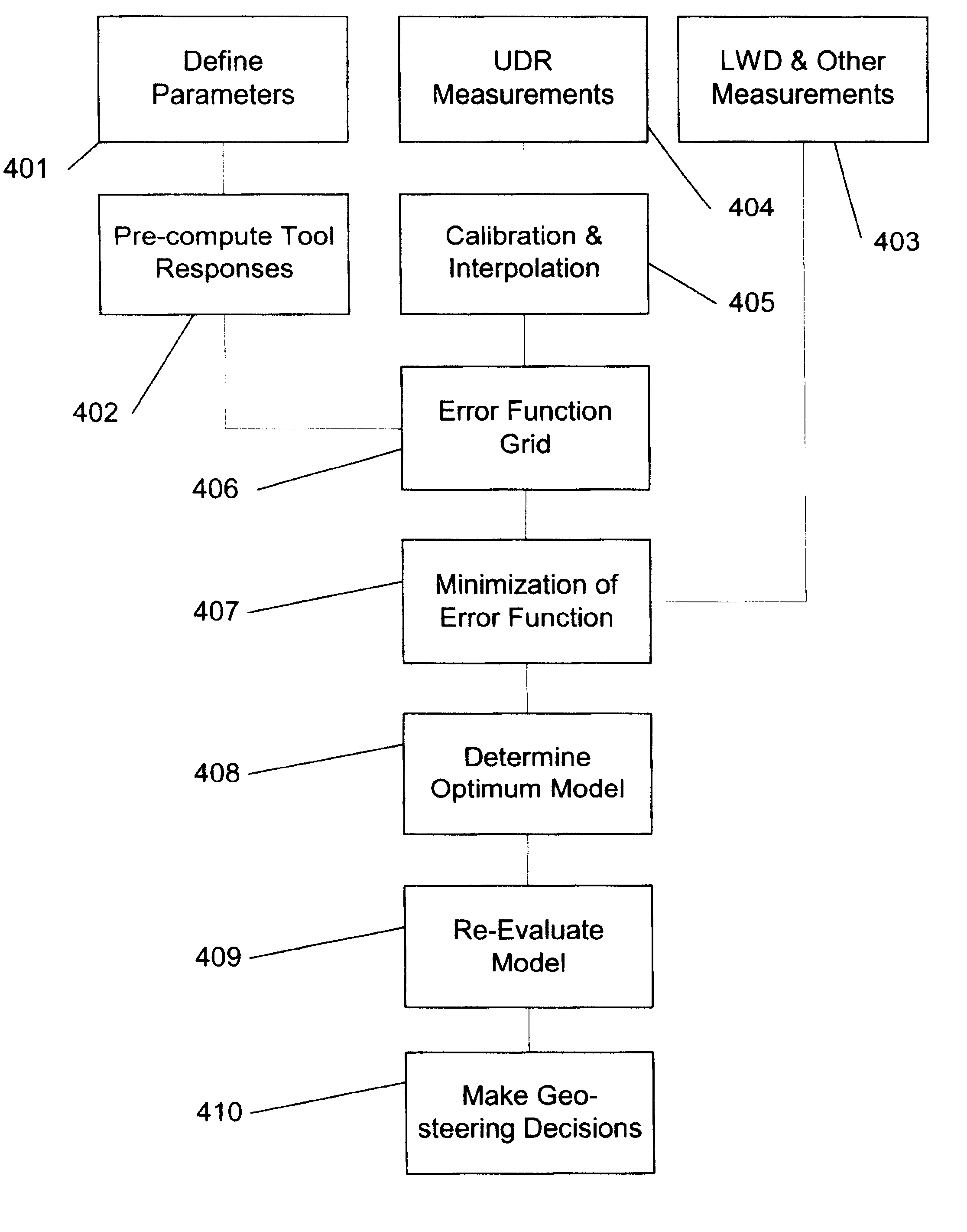
[0035]In certain embodiments, the invention relates to methods for geosteering using deep reading resistivity tools. In accordance with some embodiments of the invention, resistivity measurements are made while drilling a wellbore. The measurements are compared with the expected measurement data based on selected formation models. An optimum formation model, including the borehole location in formation layers, is determined from this comparison. Information of the borehole location is then used to control the drilling directions. In other embodiments, the invention may be used on a wireline tool to make “time lapse” measurements to determine how the formation properties have changed over time as the well is being produced. Additionally, certain embodiments of the invention relate to sensor equipment that is permanently installed in a well for permanent monitoring applications.

[0036]It is noted that the invention makes reference to “resistivity tools” and measuring a “resistivity.” I...


PUM


Abstract

A method for geosteering while drilling a formation includes generating a plurality of formation models for the formation, where each of the plurality of the formation models includes a set of parameters and a resistivity tool therein and locations of the resistivity tool differ in the plurality of the formation models. The method may also include computing predicted tool responses for the resistivity tool in the plurality of formation models, acquiring resistivity measurements using the resistivity tool in the formation, and determining an optimum formation model based on a comparison between the actual tool response and the predicted tool responses. The method may also include steering a bottom home assembly based on the optimum formation model.

Description

CROSS REFERENCE TO RELATED APPLICATIONS[0001]This application claims the priority from U.S. Provisional Application No. 60 / 319,937 filed on Feb. 11, 2003. This Provisional Application is incorporated by reference in its entirety.BACKGROUND OF INVENTION[0002]1. Field of the Invention[0003]The invention relates generally to well logging using resistivity logging tools. More particularly, the invention relates to methods for processing signals from an electro-magnetic well-logging tool to determine formation properties and a desired well path through the formation.[0004]2. Background Art[0005]Wells are generally drilled through formations in the Earth's crust so that materials trapped reservoirs in the formations, such as petroleum, can be recovered. Often a well is drilled horizontally through a reservoir to increase the drainage area in the reservoir. Because many of these formations are layered, the position of the well with respect to the boundaries of the layers can be very import...

Claims


Application Information

Patent Timeline
IPC IPC(8): E21B25/00G01J3/18E21B7/04E21B47/00G01V3/24G01V3/28
CPCE21B7/04G01V3/28E21B47/00E21B47/022E21B44/00
Inventor SEYDOUX, JEANOMERAGIC, DZEVATTABANOU, JACQUES R.
Owner SCHLUMBERGER TECH CORP
Why Eureka
Try Eureka