
Ladder stabilizer

a technology of ladder stabilizer and stabilizer, which is applied in the direction of ladders, building construction, construction, etc., can solve the problems of large number of ladder brackets, difficult installation, complex operation,

Active Publication Date: 2006-08-22
SWANN JEFFREY J
View PDF63 Cites 27 Cited by
  • Summary
  • Abstract
  • Description
  • Claims
  • Application Information

AI Technical Summary

Benefits of technology

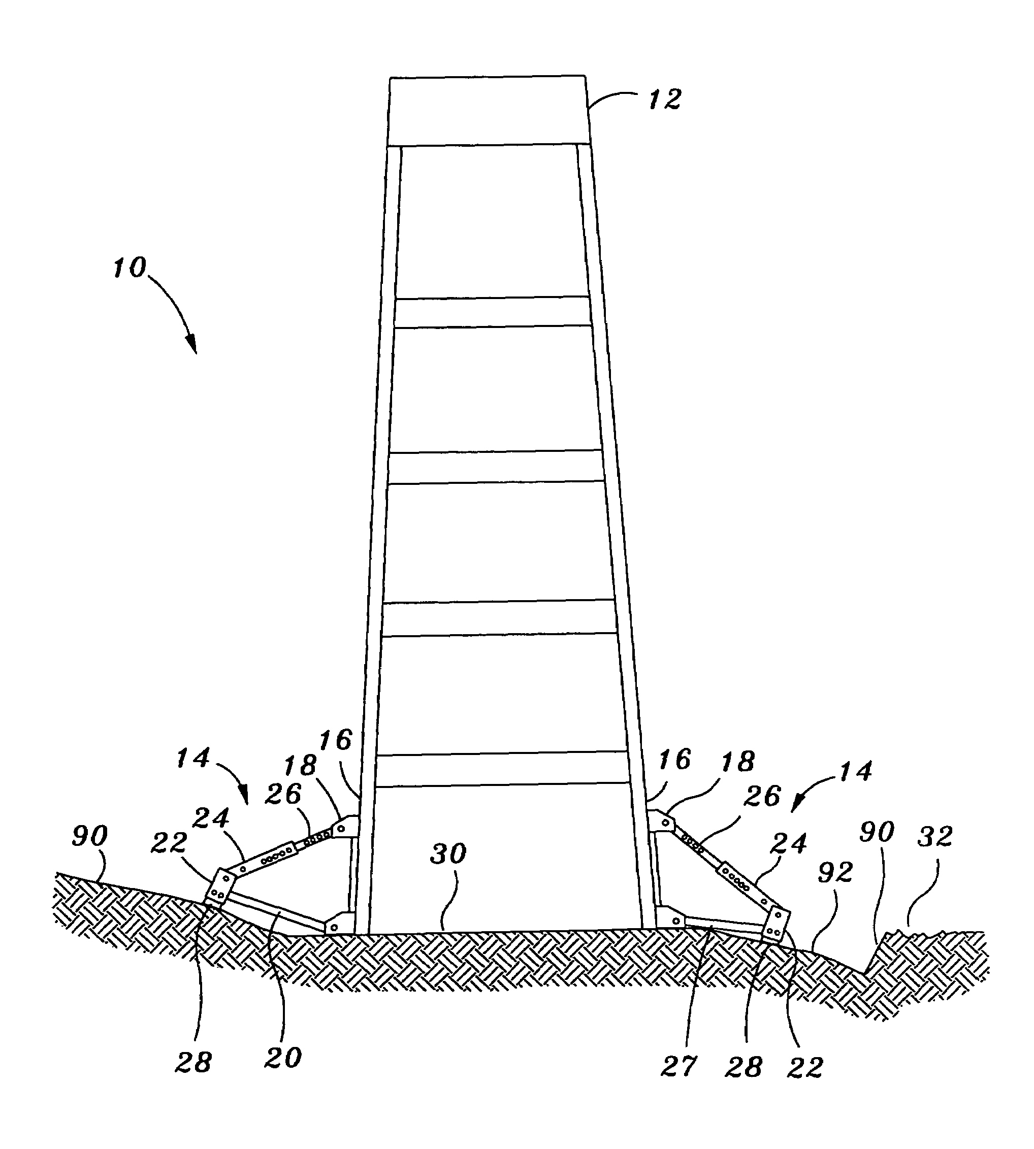
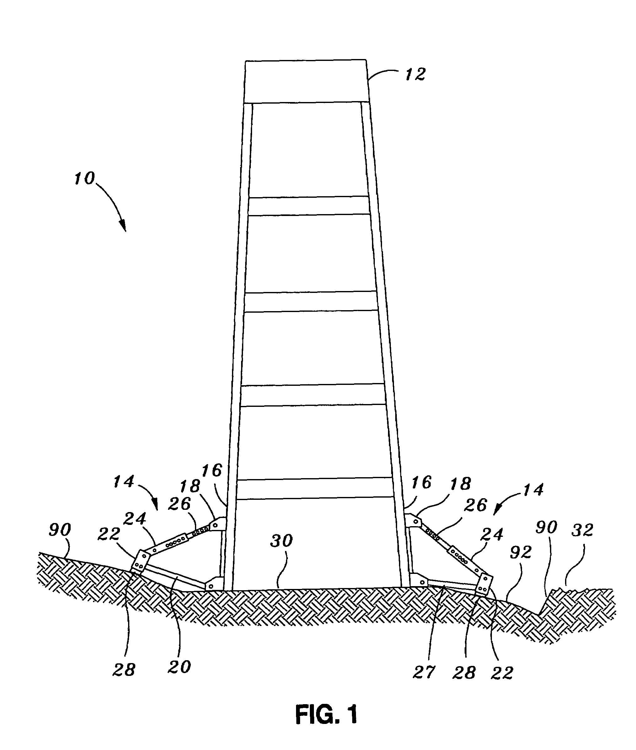
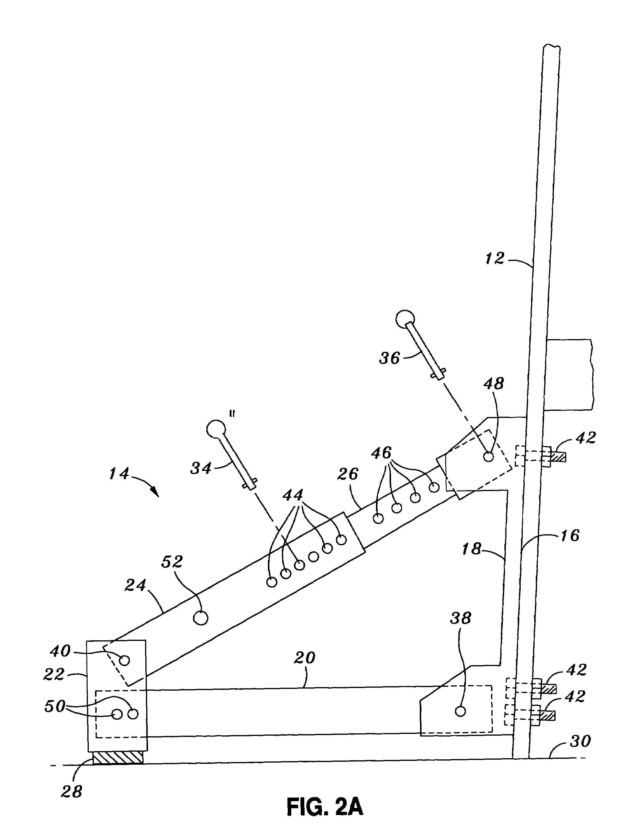
"The present invention provides a ladder stabilizer that includes a main bracket, lower arm, foot bracket, upper arm, and slide arm. The ladder stabilizer can be attached to a ladder to provide stability and prevent the ladder from tilting or shaking. The ladder stabilizer can be adjusted for different ladder configurations and can be easily attached and detached from the ladder. The technical effects of the invention include improved safety and stability for ladders, making them safer and easier to use."

Problems solved by technology

The ladder braces are often large, unwieldy, difficult to install, complex to operate, and difficult to fold and retract when storing the ladder.
The ladder braces are not effective for securing ladders from slipping or falling on uneven surfaces.
However, the meshed teeth can wear from frequent use, entailing unsafe conditions where the stabilizer no longer can lock because the teeth no longer mesh securely to prevent longitudinal movement of the tubular poles.
The Levi patent does not seem to disclose a compact device to be set up for securing the ladder from lateral movement and to be stowed away when the ladder is not in use.
The Levi patent also does not offer a simple mechanism for operating and adjusting the support to accommodate uneven surfaces.
The Severson patent does not seem to disclose a structure that would prevent twisting deflection of the side rails, which could lead to a person at the top of the ladder falling because the ladder, even with the brace, would not provide sufficient support.
Additionally, the foot actuation does not seem to provide secure, easily recognizable locking of the ladder brace to prevent inadvertent collapse of the folding ladder brace while a person is at the top of the ladder.
For example, a passerby could accidentally kick the foot-actuated ladder brace so that the brace folds up, leading to a hazardous situation for someone on the ladder.

Method used


Image

  • Ladder stabilizer
  • Ladder stabilizer
  • Ladder stabilizer

Examples


Embodiment Construction

[0031]The following detailed description is of the best currently contemplated modes of carrying out the invention. The description is not to be taken in a limiting sense, but is made merely for the purpose of illustrating the general principles of the invention, since the scope of the invention is best defined by the appended claims.

[0032]The present invention is useful for stabilizing and supporting ladders of various types to improve safety. When a person ascends the rungs of a ladder, the center of gravity rises with each step. To counteract the tendency for the ladder to fall, slip, flex near a bottom portion of a side rail, or otherwise fail to adequately support a person's weight, the present invention may serve to widely spread the weight at the ladder bottom to enhance safety. The present invention may be used wherever ladders can be used, such as for construction activities, building maintenance activities, repair activities or practically anywhere where activities must be...


PUM


Abstract

The present invention provides a method and apparatus for stabilizing a ladder for minimizing accidents. For example, a main bracket may be connected to a lower arm, a foot bracket may be connected to the lower arm, an upper arm may be connected to the foot bracket and a slide arm may be telescopically slidable inserted inside the upper arm. Pins may be inserted into holes within the main bracket, upper arm, lower arm, and slide arm to secure the ladder stabilizer. The main bracket may be attached to most ladders regardless of side rail thickness. The ladder stabilizer may accommodate varying surfaces, flat and uneven, with the ability to fold up against the vertical sides of the ladder in a small compact unit when not in use.

Description

BACKGROUND OF THE INVENTION[0001]The present invention relates generally to a safety device for a ladder and, more particularly, to an attachment adapted to be conveniently secured to either or both sides of a ladder for supporting the ladder against slipping and falling.[0002]Conventional ladder braces have stabilizing legs fastened to the ladder. The ladder braces are often large, unwieldy, difficult to install, complex to operate, and difficult to fold and retract when storing the ladder. The ladder braces are not effective for securing ladders from slipping or falling on uneven surfaces.[0003]One attempt to provide a solution to the above problems is disclosed in U.S. Pat. No. 4,949,809 to Levi, et al. (“Levi”). A locking mechanism for longitudinally fixing a first and a second tubular pole appears to comprise a plurality of spaced, parallel teeth projecting radially outward from the first tubular pole for engagement with an adjacent notch on a locking ring mounted on the second...

Claims


Application Information

Patent Timeline
Patent Type & Authority Patents(United States)
IPC IPC(8): E06C1/00E06C7/00
CPCE06C7/46
Inventor SWANN, JEFFREY J.
Owner SWANN JEFFREY J
Learn More