Tray pack and packaging structure

a packaging structure and packaging technology, applied in the field of new packaging structure, can solve the problems of not being equipped with protective functions against shock directed at the edges or corners of the packaging structure, not being able to fit the above packaging structure for packaging circuit units, and inevitably large external packages, etc., to achieve the effect of effective elastic deformation of the curved surface and better shock diffusion

Inactive Publication Date: 2006-08-22
FUJITSU LTD
View PDF13 Cites 26 Cited by
  • Summary
  • Abstract
  • Description
  • Claims
  • Application Information

AI Technical Summary

Benefits of technology

[0020]According to the above second means, the tray pack will have the same effects as that described for the first means; however, the box structure which holds the tray pack will also have the effect of protecting the contained product.
[0021]Specifically, the sustaining portions placed at the inner side of the box structure sustains the tray pack through partial contact with its outer surface at the sides, which in turn enables effective elastic deformation of the curved su

Problems solved by technology

The external package will inevitably be rather large since protection against vibration and shock is dependent upon the elasticity of the materials, with the only function of the cardboard box being to contain all these pieces together.
However, some of the above packaging structures are not fit for packaging circuit units, since they do not have the shock diffusing functions that can ensure shock absorption and cont

Method used


Image

  • Tray pack and packaging structure
  • Tray pack and packaging structure
  • Tray pack and packaging structure

Examples


first embodiment

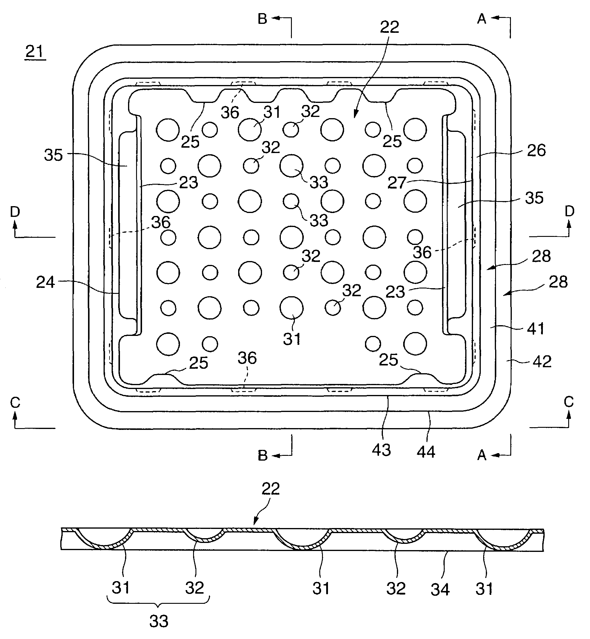
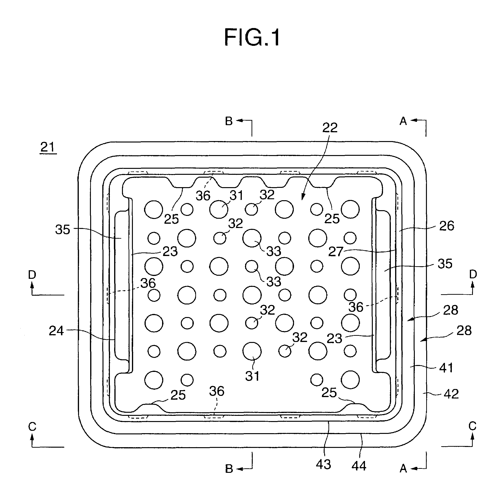
[0107]the present invention can be further described as follows: a packaging structure comprising a tray pack made of elastic material comprising:

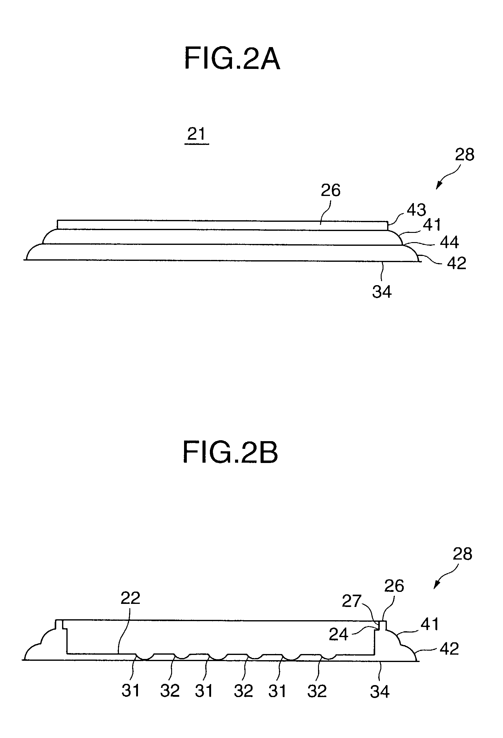
[0108]a first tray pack and a second tray pack provided with sustaining portions sustaining the areas around the contained product; a plate composed of multiple sets of protrusions / indentations having protrusions / indentations of different sizes and heights, said plate being spaced apart from the above contained product; and a curved surface formed on the outer sides of the tray pack, enabling elastic deformation around the above sustaining portions, and composed of at least a first curved surface and a second curved surface that is extended from the first curved surface; wherein:

[0109]the first tray pack and the second tray pack face opposite one another and are adjoined together to hold the contained product securely in place by fitting together concave and convex engaging portions formed at the periphery of the above first tray pack and ...

second embodiment

[0113]A packaging structure in accordance with either one of the first or second embodiment as described above, characterized in that the tray pack made of elastic material is particularly made of synthetic resin having elasticity molded into a sheet form.

[0114]A packaging structure characterized by comprising a shock absorption structure having first protrusions / indentations and at least 3 second protrusions / indentations that surround said first protrusion, wherein:

[0115]the above first protrusions / indentations and second protrusions / indentations are placed on one plane facing downward, and thus the tips of the first protrusions / indentations touching said plane and the tips of the second protrusions / indentations having some space in between said plane; and wherein:

[0116]sustaining portions are set opposite the protruding surface formed by the above first and second protrusions / indentations so that they sustain the contained product. (3)

[0117]A packaging structure as described in an...


PUM


Abstract

The object of the invention is to construct a simple packaging structure having few components and capable of protecting a contained product against shock impacts coming from all directions. To this end, the packaging structure according to the present invention is made of synthetic resin with an elastic quality molded into a sheet form, and includes a first tray pack and a second tray pack which face each other and are adjoined to hold the contained product securely in place; wherein the first and second tray packs are provided with sustaining portions sustaining the periphery of the contained product.

Description

BACKGROUND OF THE INVENTION[0001]1. Field of the Invention[0002]The present invention relates to a new packaging structure, with shock diffusion functions, convenient for transporting or storing a packaged product such as a circuit unit having a printed wiring board.[0003]Various types of communication apparatuses, information processing apparatuses, and measuring apparatuses, use circuit units having printed wiring boards, for instance, which are equipped with signal processing power having a very large capacity and great accuracy, and composed of a high density of electronic components.[0004]Such circuit units are typically transported to a site where the apparatus is to be set up in individual packages separate from each other and the rest of the apparatus. Thus, great care needs to be taken in packaging the units so as to protect them from various vibration and shock impacts during transportation of the units, and during storage in a warehouse. Particularly, the packaged units w...

Claims


Application Information

Patent Timeline
IPC IPC(8): B65D81/02B65D1/34B65D85/30B65D5/50B65D5/66B65D81/133B65D85/86
CPCB65D5/5021B65D81/133B65D81/025B65D5/6664B65D51/244
Inventor SAKAI, SHUHEIAKIMOTO, MIYUKIFUJII, KATSUYAKATAGIRI, HIROSHIKUSUDA, KIYONORI
Owner FUJITSU LTD
Why Eureka
Try Eureka