
Bar code reader stand

a bar code reader and stand technology, applied in the field of stands, can solve the problems of permanent marring of the table top, impracticality for many applications, and impracticality for us

Inactive Publication Date: 2006-08-22
SOC DES LOTERIES VIDEO DU QUEBEC
View PDF13 Cites 27 Cited by
  • Summary
  • Abstract
  • Description
  • Claims
  • Application Information

AI Technical Summary

Problems solved by technology

Since the apparatus requires the bar code to be held in a vertical position, it is impractical for many applications.
As such, they are impractical for use in temporary situations where quick installation is desirable and where the use of screws or bolts would cause undesirable permanent marring of table tops.
However, using a hand held scanner for extended periods may lead to fatigue, and the positioning of a scanner by hand may not consistently provide quick accurate readings.
Such adjustment would likely be made using trial and error.
Furthermore, in an active environment, it is likely that the orientation of the bar code reader would gradually deviate from its optimal orientation, either due to jostling or gravity.

Method used


Image

  • Bar code reader stand
  • Bar code reader stand
  • Bar code reader stand

Examples


Embodiment Construction

Definitions

[0020]The term “coded medium” is used to describe any object having associated therewith a bar code. This bar code provides a means for identifying the identity of the object. The object can be anything that is to be identified, for example a can of soup, car part, lottery ticket or any other item.

[0021]The term “reading surface” is used to describe an area where a coded medium is positioned to enable a bar code reader to scan a bar code associated with the coded medium.

[0022]Unless defined otherwise, all technical and scientific terms used herein have the same meaning as commonly understood by one of ordinary skill in the art to which this invention belongs.

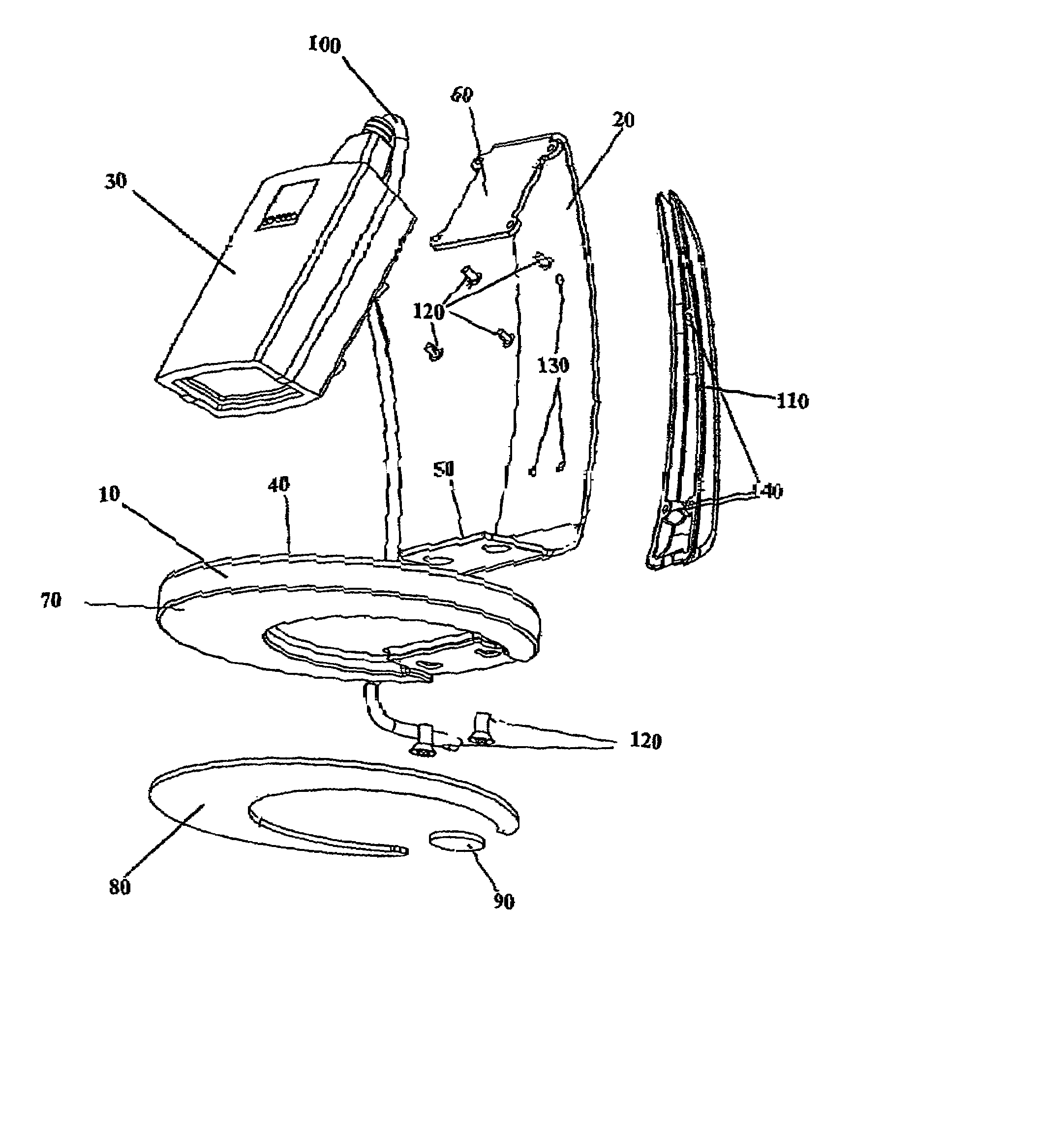
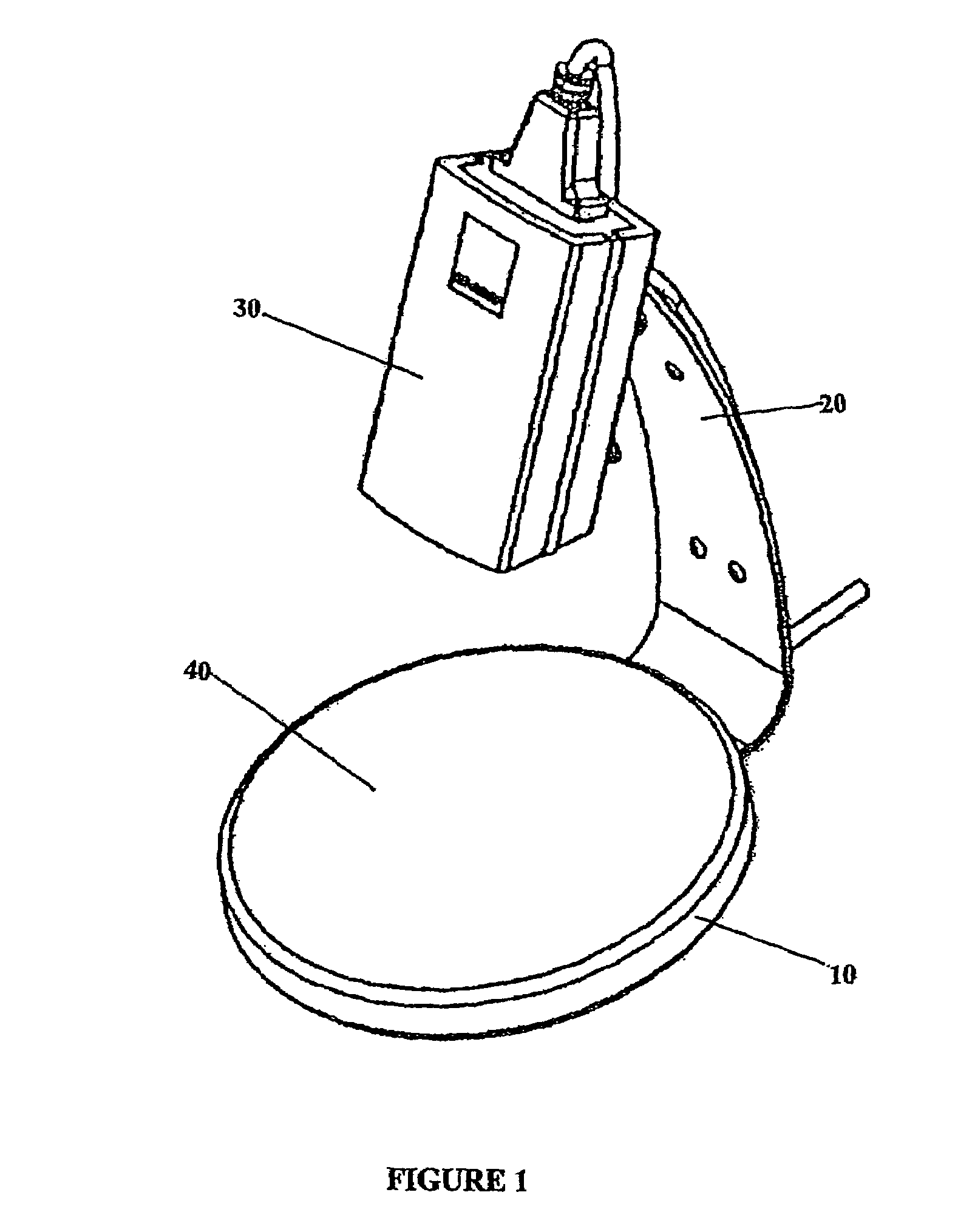
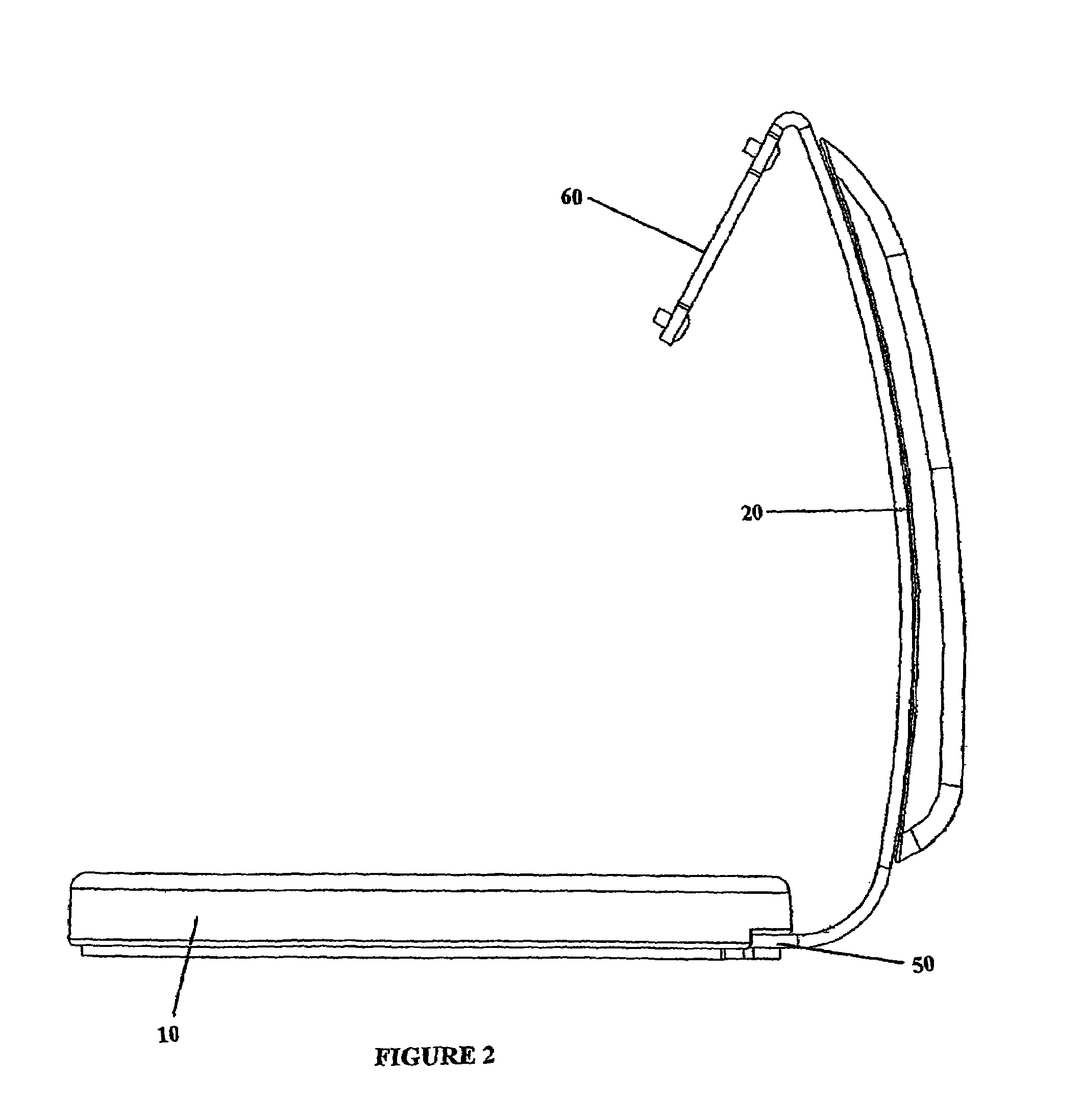
[0023]The present invention provides a bar code reader support stand that is portable and easy to set up in addition to being stable and not easily tipped. The support stand provides a reading surface on which to place a coded medium. The support stand further provides a securing area for mounting a bar code reader, s...


PUM


Abstract

The present invention provides a bar code reader support stand that is portable and easy to set up in addition to being stable and not easily tipped. The support stand provides a reading surface on which to place a coded medium. The support stand further provides a securing area for mounting a bar code reader, such that said bar code reader is held at a predetermined and fixed distance and angle with respect to said reading surface. The fixed position and orientation of the bar code reader with respect to the reading surface allows for a consistently reliable reading of the coded medium. Installation and usage of the device can be more efficient since the user need not adjust the bar code reader orientation at the time of set-up, nor re-adjust it during the course of usage. The design of the weight-stabilised base allows the device to be set up and used in an active environment without the need to rigidly connect it to a table top by means of screws or bolts. The bar code reader stand according to the present invention may also include a protective structure for protecting the cable interconnected with the bar code reader. Said protective structure can provide protection for the cable itself as well as to the point of connection between said cable and the electronic device or bar code reader.

Description

CROSS REFERENCE TO RELATED APPLICATION(S)[0001]This application claims the benefit of priority under 35 U.S.C. § 119(e) of U.S. Ser. No. 60 / 437,449, filed Jan. 2, 2003, the entire content of which is incorporated herein by reference.BACKGROUND OF THE INVENTION[0002]1. Field of the Invention[0003]The present invention pertains to the field of stands and more particularly to stands for bar code readers.[0004]2. Background Information[0005]The use of optical bar codes for identifying a wide variety of goods is well established, and such codes have proliferated with the increased use of automatic data processing systems. This has produced a strong demand for reliable systems which will rapidly and accurately read the information provided by the codes, and transfer that information to a computer, a data storage system, a read-out display, a control device or the like. Extremely fast and accurate reading of these codes is particularly necessary if the advantages of computer control are re...

Claims


Application Information

Patent Timeline
IPC IPC(8): G06K7/10A47F9/04
CPCA47F9/046G06K7/10881G06K7/10861
Inventor BOUCHER, CHRISTIANEGARCEAU, ROGERGRONDINES, ALAIN
Owner SOC DES LOTERIES VIDEO DU QUEBEC
Learn More