Self-aligning bearing

Inactive Publication Date: 2006-08-22
KOYO SEIKO CO LTD
View PDF11 Cites 11 Cited by
  • Summary
  • Abstract
  • Description
  • Claims
  • Application Information

AI Technical Summary

Benefits of technology

[0023]In this case, a full complement cylindrical roller type, in which the cylindrical rollers are arranged side by side in a circumferential direction without using the cage for holding

Problems solved by technology

Accordingly, an outer shape of the self-aligning bearing is large-sized, and it is unavoidable to change design of an axle box.
However, in the case of restricting the entire width and the outer diameter of the outer ring in the axial dir

Method used


Image

  • Self-aligning bearing
  • Self-aligning bearing
  • Self-aligning bearing

Examples


embodiment 1

[0040]First, a self-aligning bearing 4a, in accordance with a conventional embodiment 1 shown in FIG. 5 is a so-called single row cylindrical roller bearing with aligning ring, and is structured such that radially inward flanges 15A and 15B are provided in both ends of a single outer ring 11 in an axial direction, a radially outward flange 16 is provided in one end of a single inner ring 12 in an axial direction, and a flange ring 18 is attached.

embodiment 2

[0041]Further, a self-aligning bearing 4b, in accordance with a conventional embodiment 2 shown in FIG. 6 is a so-called double row combined cylindrical roller bearing with aligning ring, and is structured such that radially inward flanges 15A and 15B are provided in inner ends of two outer rings 11A and 11B in an axial direction, and radially outward flange 16A and 16B are provided in both ends of two inner rings 12A and 12B in an axial direction. Two outer rings 11A and 11B are connected by a pin, or the like (not shown).

[0042]In this case, in the case of the conventional embodiment 1 mentioned above, for the purpose of securing a strength of the flanges 15A and 15B of the outer ring 11, an outer size is increased.

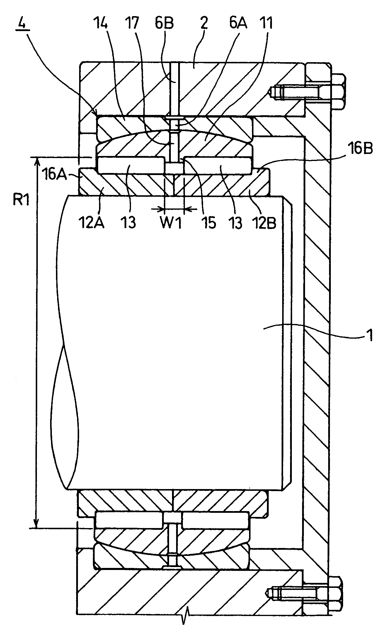
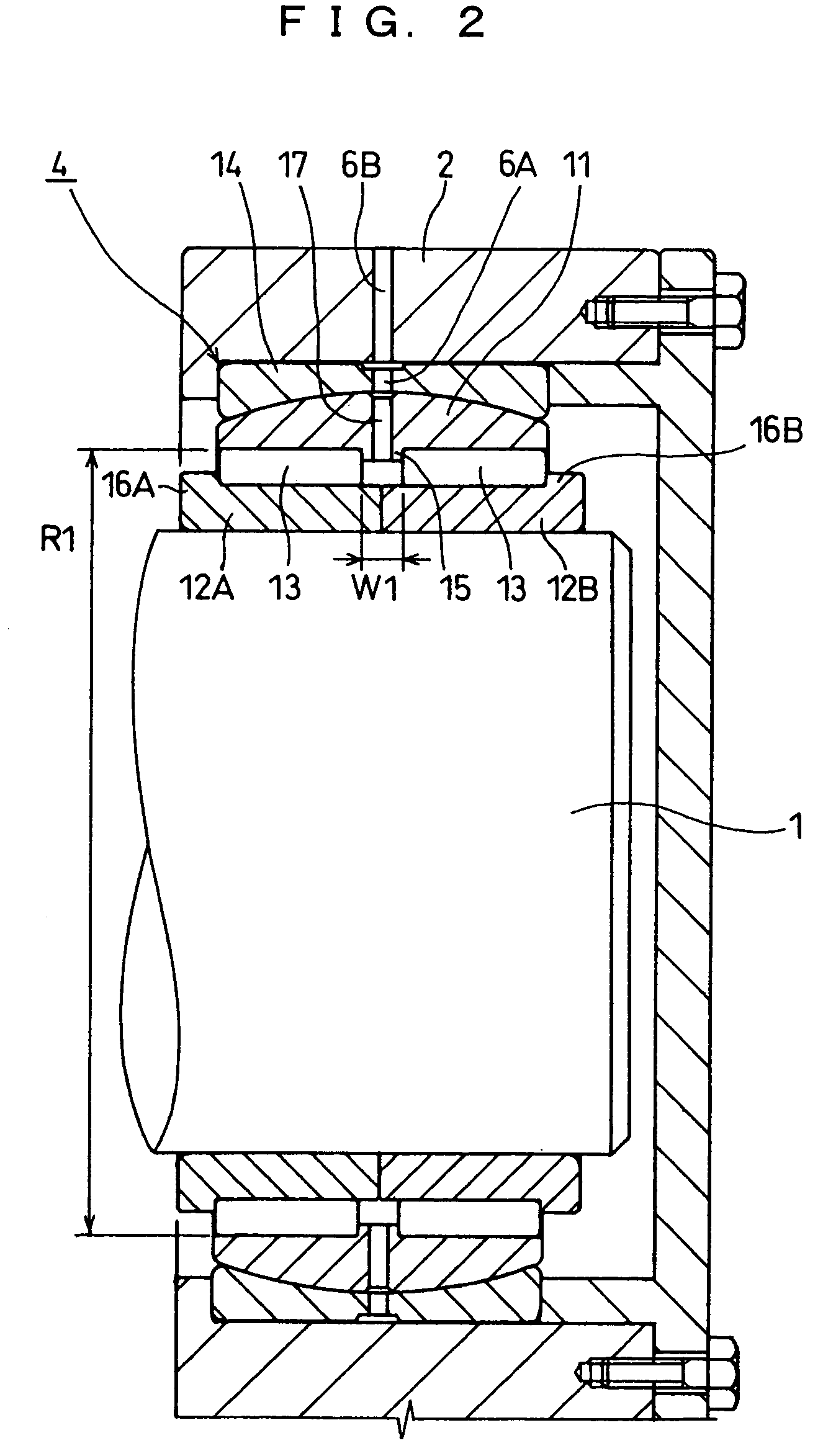
[0043]In accordance with the present embodiment, since only one flange 15 of the outer ring 11 is provided in the thickest intermediate portion in the axial direction, the strength of the flange 15 can be strengthened without increasing the thickness of both ends of the ...


PUM


Abstract

In a self-aligning bearing positioning and supporting one end of a rotation shaft in an axial direction and allowing the rotation shaft to bend, the bearing is structured as a double row cylindrical roller bearing with aligning ring, a first row of cylindrical roller group is positioned by being held in an axial direction between a radially inward flange provided in an intermediate portion in an axial direction of an outer ring having an outer peripheral surface formed in a spherical surface shape, and a flange provided in one outer end of two inner rings, and a second row of cylindrical roller group is positioned by being held in the axial direction between the flange of the outer ring and a flange provided in another outer ends of the two inner rings.

Description

TECHNICAL FIELD[0001]The present invention relates to a self-aligning bearing, for example, for supporting a fixed side of a roll shaft of a carrying system in a continuous casting equipment.BACKGROUND ART[0002]The roll shaft of the carrying system in the continuous casting equipment is bent, in accordance with passing of a work, such as a high temperature slab, or the like. Accordingly, both ends of the roll shaft are supported by a self-aligning bearing. As the self-aligning bearing for supporting the roll shaft mentioned above, there is employed a spherical roller bearing having a spherical roller, a cylindrical roller bearing with aligning ring having an outer ring, in which an outer peripheral surface is formed in a spherical shape, or the like. The cylindrical roller bearing with aligning ring can increase a load rating.[0003]The roll shaft is structured such as to extend in an axial direction, in accordance with the passing of the high temperature work, and contract in the ax...

Claims


Application Information

Patent Timeline
IPC IPC(8): F16C23/08F16C13/06F16C19/28F16C19/48F16C33/58F16C33/60
CPCF16C19/28F16C19/48F16C33/605F16C33/58F16C23/084
Inventor MASUI, TAKASHINUMADA, YOUICHIKAWAKAMI, TOSHIKAZUMIYOSHI, KEIICHI
Owner KOYO SEIKO CO LTD
Why Eureka
Try Eureka