System and method for inductance based position encoding sensorless SRM drives

a position encoding and sensorless technology, applied in the direction of electronic commutators, motor/generator/converter stoppers, dynamo-electric converter control, etc., can solve the problems of expensive sensors and reliability problems

Inactive Publication Date: 2006-08-22
TEXAS A&M UNIVERSITY
View PDF21 Cites 8 Cited by
  • Summary
  • Abstract
  • Description
  • Claims
  • Application Information

AI Technical Summary

Benefits of technology

[0016]A switched reluctance system is also provided. The system includes a switched reluctance machine having a rotor and a plurality of stator phases. A drive switches each stator phase current. A controller supplies control signals to the drive. The controller receives at least one sensed machine parameter from the switched reluctance machine. The controller generates control signals based on a rotor position determined from the sensed machine parameter and from a mathematical model based on inductance values measured for at least one of the stator phases, the mathematical model relating the sensed machine parameter with rotor position.
[0017]A method of controlling a switched reluctance machine is also provided. At least one active phase of the switched reluctance machine is modeled to produce a model representing dynamic magnetic machine characteristics. At least one of active voltage and current of the at least one active phase is measured and the model solved to obtain rotor position. Machine control signals are determined based on the rotor position.
[0018]A controller for a switched reluctance machine is also provided. The controller implements a model of at least one active phase of the switched reluctance machine representing dynamic magnetic machine characteristics. The controller determines machine control signals based on rotor position obtained by numerically solving the model with at least one of measured active phase voltage and current.

Problems solved by technology

Also, there are certain applications, such as in compressors, where the ambient conditions do not allow the usage of external position sensors.
However, these sensors are expensive and experience reliability problems.

Method used


Image

  • System and method for inductance based position encoding sensorless SRM drives
  • System and method for inductance based position encoding sensorless SRM drives
  • System and method for inductance based position encoding sensorless SRM drives

Examples


Embodiment Construction

)

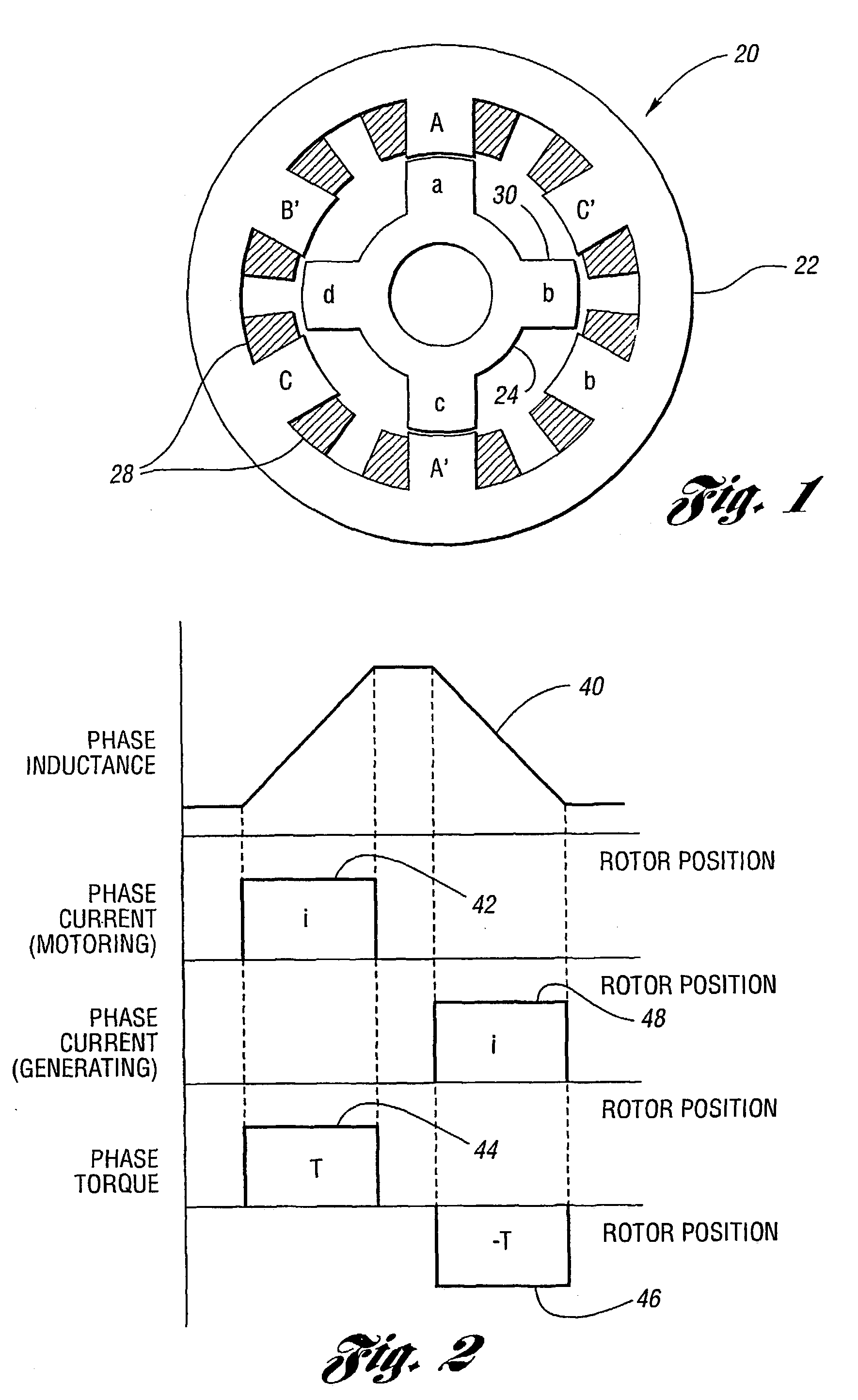
[0031]Referring to FIG. 1, a diagram of a cross-sectional view of a three-phase switched reluctance machine is shown. A switched reluctance machine (SRM), shown generally by 20, includes stator 22 and rotor 24 which turns within stator 22. Stator 22 includes a plurality of stator phases, one of which is labeled 26. Each stator phase is driven by stator windings 28, shown cross-hatched. Rotor 24 includes a plurality of poles, one of which is indicated by 30. SRM 20, in the example shown, has six phases 26 and four poles 30. Typically, opposing phases 26 are simultaneously supplied with phase current. SRM 20 is, therefore, considered to be a three-phase machine. Opposing phases 26 may be conveniently labeled with the same letter. Phases 26 in SRM 20 are labeled A, A′, B, B′, C and C′. Poles 30 in SRM 20 are labeled a, b, c and d.

[0032]Referring now to FIG. 2, a diagram of idealized inductance, current and torque waveforms during motoring / generating operations is shown. Plot 40 illust...


PUM


Abstract

A controller (72) for a switched reluctance machine (20) implements a model of at least one active phase representing dynamic magnetic machine characteristics. The controller (72) determines machine control signals based on rotational position obtained by numerically solving the model with measured machine operating parameters. The model may be implemented as the sum of orthogonal functions relating active phase voltage and current with constants derived from phase inductance to obtain the rotor angle.

Description

RELATED APPLICATIONS[0001]This application claims priority under 35 U.S.C. §119 of PCT application number PCT / US01 / 09986, filed Mar. 29, 2002, entitled “System and Method for Inductance Based Position Encoding Sensorless SRM Drives” which claims priority to provisional application No. 60 / 193,012 filled Mar. 29, 2000.BACKGROUND OF THE INVENTION[0002]1. Field of the Invention[0003]This invention relates generally to Switched Reluctance Machines (SRMs) and, more particularly, to a system and method for inductance based position encoding for sensorless SRM drives.[0004]2. Background Art[0005]Switched reluctance machine (SRM) drives have been considered as a possible alternative to conventional drives in several variable speed drive applications because of the many advantages associated with SRM systems. The performance of an SRM drive can be tailored to suit several applications through appropriate control. Other advantages include constructional simplicity of the machine such as, for e...

Claims


Application Information

Patent Timeline
Patent Type & Authority Patents(United States)
IPC IPC(8): H02P1/46H02P23/00H02P25/00H02P3/18H02P6/00H02P6/18H02P25/08
CPCH02P25/083H02P6/18H02P25/089
Inventor EHSANI, MEHRDADGOPALAKRISHNAN, SURESH
Owner TEXAS A&M UNIVERSITY
Why Eureka
Try Eureka