Computerized machine controller diagnostic system

a machine controller and diagnostic system technology, applied in the direction of program control, setting time indication, electric unknown time interval measurement, etc., can solve the problems of considerable magnitude, low realization of asset utilization, and difficult diagnosis of malfunctions on machinery so controlled

Inactive Publication Date: 2006-06-27
WILSON DIAGNOSTIC SYST
View PDF44 Cites 61 Cited by
  • Summary
  • Abstract
  • Description
  • Claims
  • Application Information

AI Technical Summary

Benefits of technology

[0064]Yet another type of display that may be produced by the system of the present invention on the viewing component is that of a machine status display. The operational status of a machine is preferably displayed in the form of a stack-light that is color-coded to indicate different operational statuses. In a preferred embodiment, numerous machines and / or virtual machines have been defined and are monitored by the system of the present invention allowing the user to have a simultaneous overview of each machine, or virtual machine, status by presenting a stack-light for each machine on a single display.

Problems solved by technology

The very power of the control systems themselves has lead to a problem of considerable magnitude for American industry.
Although productive in their own right, these complex control systems have given rise to a significant problem in that the diagnosis of malfunction on machinery so controlled may be very difficult.
This low realization of asset utilization is prevalent even among the more capable manufacturers such as in the automotive industry.
The underlying problem with the extensive downtime of many machines controlled by control systems is that the logic in the control system is so extensive and so complex.
Even experienced and capable electricians and technicians have great difficulty in finding the root cause of an operating malfunction.
Electricians and technicians can not possibly become familiar with all of this program logic.
When they are confronted with an operating problem on a given machine they may spend hours trying to understand enough of the control system logic so that they might find the source of the problem.
It is not unusual to experience hours of diagnostic time only to find that the actual repair takes just a few minutes.
Programs to educate electricians have not been fruitful because the body of information that they need to understand is so large and, even worse, is constantly changing.
Even further, the electricians and technicians are frequently moved from one department to another exacerbating the problem of education.
It is estimated that the United States problem on downtime due to the diagnostic period on programmable controlled machinery is in the order of more than one hundred billion dollars annually.
When one of the input devices in the above example fails, the machine will stop sequencing.
In a very large percentage of the automatic cycle interruptions an input has failed to come on at the desired time, or an output has failed to operate and has not sent its signal to the controller.
The problem the diagnostician is faced with is that many machines have hundreds of inputs and outputs operated on by several thousand lines of program code.
This could be caused by a faulty proximity switch or by a mechanical malfunction whereby no part was actually loaded.
Even the machines that have better error messaging may have several messages on screen by the time the electrician arrives.
The electrician may see a part in the clamping fixture but it is not possible to determine where the automatic cycle actually stopped.
The usual case is that there are many possibilities, and in the typical mode of operation the person responsible for the diagnostics has no way of determining which is the most probable source of the problem and which is the least probable cause.
Programmable logic controllers do not keep any history of their operations so the electrician has little information to tell why the machine stopped.
Even further, in most factories the electrician may not even be sure of the nature of the sequence of operation of the machine.
The electrician probably does not know the address of the inputs and outputs so it is not possible to do a simple inspection of the machine to tell why it has stopped operating.
Even if the machine has an error messaging system, it often has hundreds of possible messages many of which do not give a clear description of the nature of the error.
The diagnostic process is often trial and error.
First, the logic is usually very complicated, much more complicated than the simple example above, and second, the state of the inputs and outputs in the controller at the time of diagnostic examination is not the same as the state that existed at the exact time when the machine stopped.
While each of the above-described patents has been somewhat useful in determining the cause of an error or failure within a machine or process, they present the user with a complex system that is, of its ownself, difficult to learn and implement.

Method used


Image

  • Computerized machine controller diagnostic system
  • Computerized machine controller diagnostic system
  • Computerized machine controller diagnostic system

Examples


Embodiment Construction

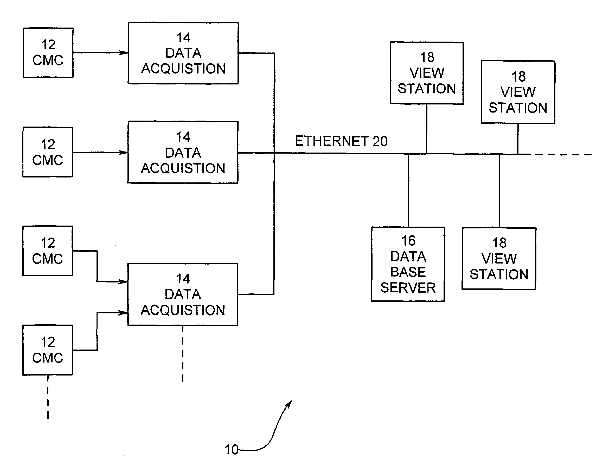
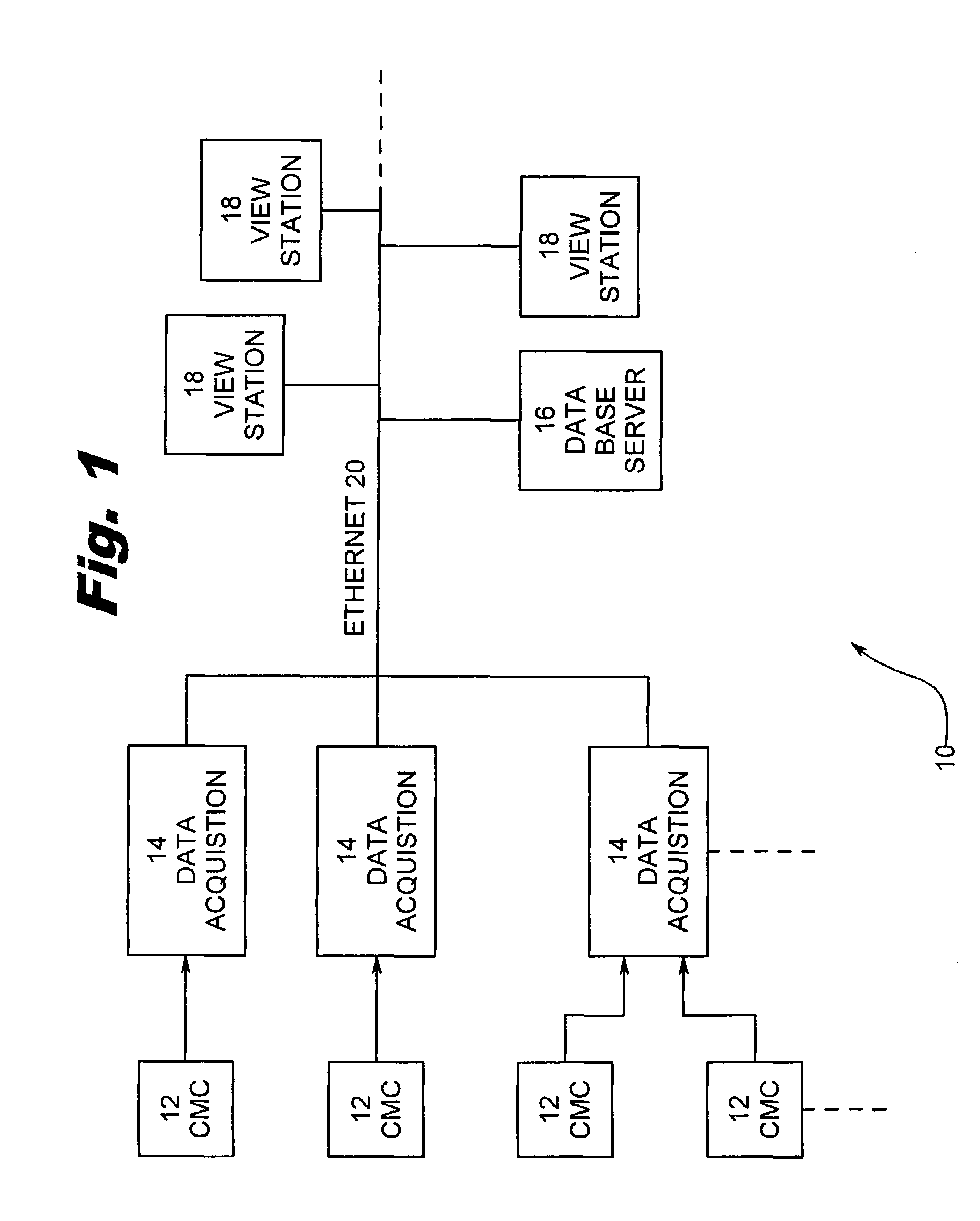
[0083]A computerized machine controller (CMC) diagnostic system of the present invention is described hereinbelow. The CMC diagnostic system operates to acquire and monitor status changes in the input / output (I / O) tables of a PLC controlled machine or process. The system determines whether the current I / O tables of the machine or process have deviated from the expected status and provides notice to the user of such a deviation. If the deviation has resulted in a machine or process shut-down, the system operates to provide the user with an indication of the most probable cause of shut-down. The CMC diagnostic system provides the user with numerous additional tools to aid in the efficiency of monitoring and running the machine or process to which CMC diagnostic system is applied. It should be noted that the term machine is used in a generic sense and connotes a complete machine, a subset thereof (virtual machine), or a combination of different machines.

I. System Components

[0084]FIG. 1...


PUM


Abstract

A computerized machine control (CMC) diagnostic system communicates with a computerized machine controller that utilizes a control program to control the operation of a machine through the use of a plurality of digital channels. In general terms, the system includes a data acquisition component, a data storage component and a viewing component. The data acquisition component queries and acquires time-based transition data about the plurality of digital channels. The data storage component stores the acquired transition data in order to establish an historical pattern of the transition data that can be compared to currently acquired transition data. The historical pattern of transition data is established independently of the control program. Upon comparison of the current transition data to the expected, historical pattern of transition data, a determination about the operational status of the machine being controlled can be made. The operational status can then be displayed on the viewing component.

Description

CLAIM TO PRIORITY[0001]The present application claims priority to United State Provisional Patent Application No. 60 / 151,499, filed Aug. 30, 1999 and entitled “PLC Diagnostic Device and Method”, to U.S. Provisional Patent Application No. 60 / 180,936, filed Feb. 8, 2000 and entitled “PLC Diagnostic Device and Method”, and to U.S. Provisional Patent Application No. 60 / 189,945, filed Mar. 16, 2000 and entitled “Programmable Logic Controller Diagnostic System and Method.” The contents of each of the three above-identified provisional patent applications is hereby incorporated by reference.FIELD OF THE INVENTION[0002]The present invention relates to machine and process control systems and, more particularly, to a diagnostic tool for the monitoring of those machine and process control systems.BACKGROUND OF THE INVENTION[0003]Manufacturers in the United States are making extensive use of computerized machine control systems including programmable logic controllers (PLCs), personal computers...

Claims


Application Information

Patent Timeline
Patent Type & Authority Patents(United States)
IPC IPC(8): G06F17/00
CPCG05B19/058G05B2219/31435G05B2219/32371Y02P90/02
Inventor WILSON, DENNIS C.DEVILEY, BRIAN
Owner WILSON DIAGNOSTIC SYST
Why Eureka
Try Eureka