
Image processing apparatus and image processing method

a technology of image processing and image processing, applied in the direction of digital output to print units, digitally marking record carriers, instruments, etc., can solve the problems of monopolization of apparatuses and other users being unable to use apparatuses while setting operation

Inactive Publication Date: 2006-08-22
CANON KK
View PDF29 Cites 7 Cited by
  • Summary
  • Abstract
  • Description
  • Claims
  • Application Information

AI Technical Summary

Benefits of technology

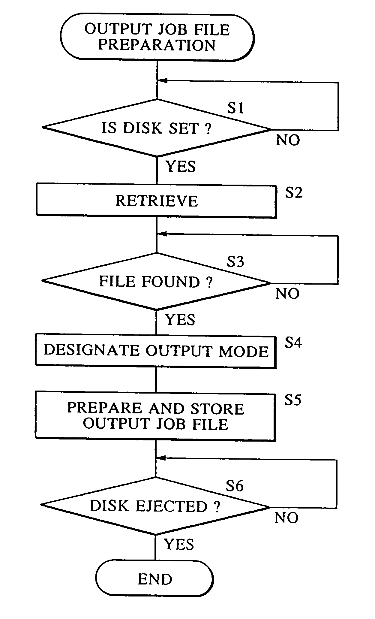
The present invention aims to provide an image processing apparatus and method that can prevent monopolization and allow for desired output modes of image data. It also aims to make the outputting of image data in a desired mode simple and easy. Additionally, the invention seeks to distribute the processing related to outputting image data among other devices. To achieve these objectives, the invention provides an image processing apparatus that can detect the presence of a detachable storage medium containing image data and output mode data, and output the image data in the desired output mode without any designation from the apparatus. The invention also provides an image processing method that includes steps of storing image data on a detachable storage medium, storing output mode data for the image data in a different apparatus, and loading the storage medium in the image data output apparatus to output the image data in the desired output mode without any designation from the apparatus.

Problems solved by technology

However, when manipulating the operating section to set the desired output mode, other users cannot use the apparatus while the setting operation is being performed.
That is, the apparatus is monopolized during that time by the user who is performing the setting operation.

Method used


Image

  • Image processing apparatus and image processing method
  • Image processing apparatus and image processing method
  • Image processing apparatus and image processing method

Examples


Embodiment Construction

[0029]An embodiment of the present invention will now be described in detail with reference to the drawings.

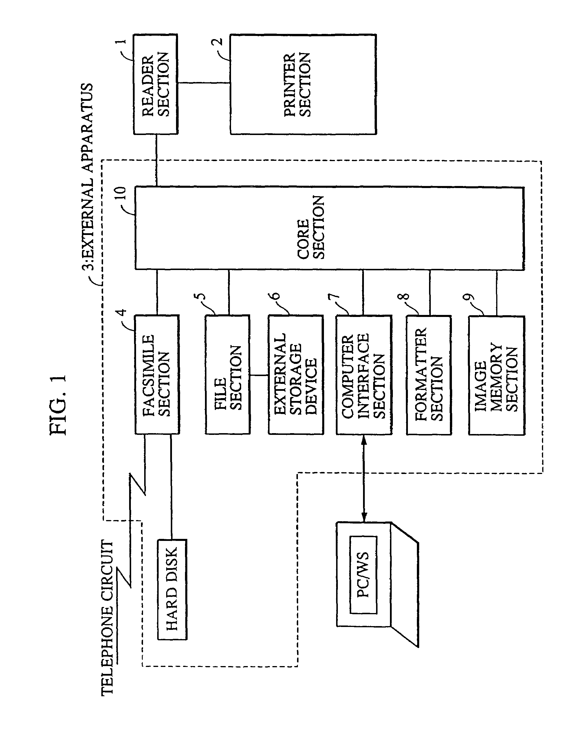
[0030]FIG. 1 is a block diagram showing the system configuration of a compound image input / output apparatus combining a plurality of functions.

[0031]In FIG. 1, a reader section 1 is an image input device for reading the images of originals to output image data. A printer section 2 is an image output device which has cassettes for a plurality of kinds of recording paper and which prints out image data on recording paper as visual images in response to a print command.

[0032]An external apparatus 3 is electrically connected to the reader section 1 and has various functions. That is, the external apparatus 3 includes a facsimile section 4, a file section 5, an external storage device 6 connected to the file section 5, a computer interface section 7 for connection to a computer, a formatter section 8 for converting information transmitted from the computer into visual images, an im...


PUM


Abstract

When reading image data stored on a detachable storage medium such as a magneto-optical disk and outputting the data using an image outputting device, data regarding modes in which the image data is to be output is stored in advance on a storage medium by an apparatus such as a personal computer, for example, which is different from the image outputting device. By loading the storage medium in the image outputting apparatus, the image data is read out and output in accordance with the stored output mode data, whereby it is possible to prevent the image outputting apparatus from being monopolized for a long period of time and to output data easily in a desired output mode.

Description

[0001]This application is a division of application Ser. No. 09 / 322,177, filed on May 28, 1999, now U.S. Pat. No. 6,963,410, which is a continuation of application Ser. No. 08 / 528,423 filed on Sep. 14, 1995, now U.S. Pat. No. 5,923,437 issued Jul. 13, 1999.BACKGROUND OF THE INVENTION[0002]1. Field of the Invention[0003]The present invention relates to an image processing apparatus and an image processing method for processing image data and, in particular, to an image processing apparatus and an image processing method that allow image data to be output in a desired mode.[0004]2. Description of the Related Art[0005]An electronic image filing apparatus has been known which stores input image data as files in a memory that is capable of electrical storage, making it possible for the image data to be managed in files.[0006]Conventional electronic image filing apparatuses, used, for example, on a stand-alone basis, are comprised of a scanner for reading original document images, a print...

Claims


Application Information

Patent Timeline
Patent Type & Authority Patents(United States)
IPC IPC(8): G06F15/00G06F17/30H04N1/00H04N1/23H04N1/32
CPCH04N1/00482H04N1/00965H04N1/0097H04N1/2158H04N1/2307H04N1/2369H04N1/32358H04N1/32443H04N1/32496H04N1/0096H04N2201/33321H04N2201/0074H04N2201/0081H04N2201/0082H04N2201/0086H04N2201/0087H04N2201/3216H04N2201/3242H04N2201/3274H04N2201/3288
Inventor ITOH, HIROHIKO
Owner CANON KK
Learn More