Set for installing an intracardiac stimulation or defibrillation lead equipped with a screw

a technology of intracardiac stimulation or defibrillation and screw, which is applied in the direction of external electrodes, internal electrodes, therapy, etc., can solve the problems of jerking or jolting movement (not a smooth rotation), complicated procedure, and accumulated constraints that are released, and achieve any significant risk for patients

Inactive Publication Date: 2006-08-22
SORIN CRM
View PDF8 Cites 18 Cited by
  • Summary
  • Abstract
  • Description
  • Claims
  • Application Information

AI Technical Summary

Benefits of technology

[0019]Advantageously, the torque limiting characteristic allows in particular the set of the invention to be usable with a very large variety of screw-in leads, where the screw is or is not retractable. Yet another advantage is that the mechanism of the present invention is completely reversible, thus allowing, if necessary, a modification of the point of implantation and a withdrawing of the lead without any significant risk for the patient.

Problems solved by technology

First, it requires the use of two different stylets, which complicates the procedure because it is necessary to withdraw the screwdriver-stylet to be able to insert the stylet to be inflated (with the bulge).
This disadvantage is further accentuated when, for a better placement of the lead-head, the surgeon has deformed the stylet before insertion by bending it a few centimeters away from the lead-head, in order to better conform to the configuration of the cardiac cavity.
A third disadvantage is that the friction of the sheath on the wall of the vein produces during the rotational movement an accumulation of constraints that are released suddenly.
It results in a jerking or jolting movement (not a smooth rotation) that is very awkward for the surgeon.
But these devices either use a relatively complex special tool to carry out the combined movement of deployment and screwing, or work to impart a rotational movement to the sheath of the lead-body always with the risk to form loops and to displace the point of implantation before the lead-head can be anchored in the endocardium.

Method used


Image

  • Set for installing an intracardiac stimulation or defibrillation lead equipped with a screw
  • Set for installing an intracardiac stimulation or defibrillation lead equipped with a screw
  • Set for installing an intracardiac stimulation or defibrillation lead equipped with a screw

Examples


Embodiment Construction

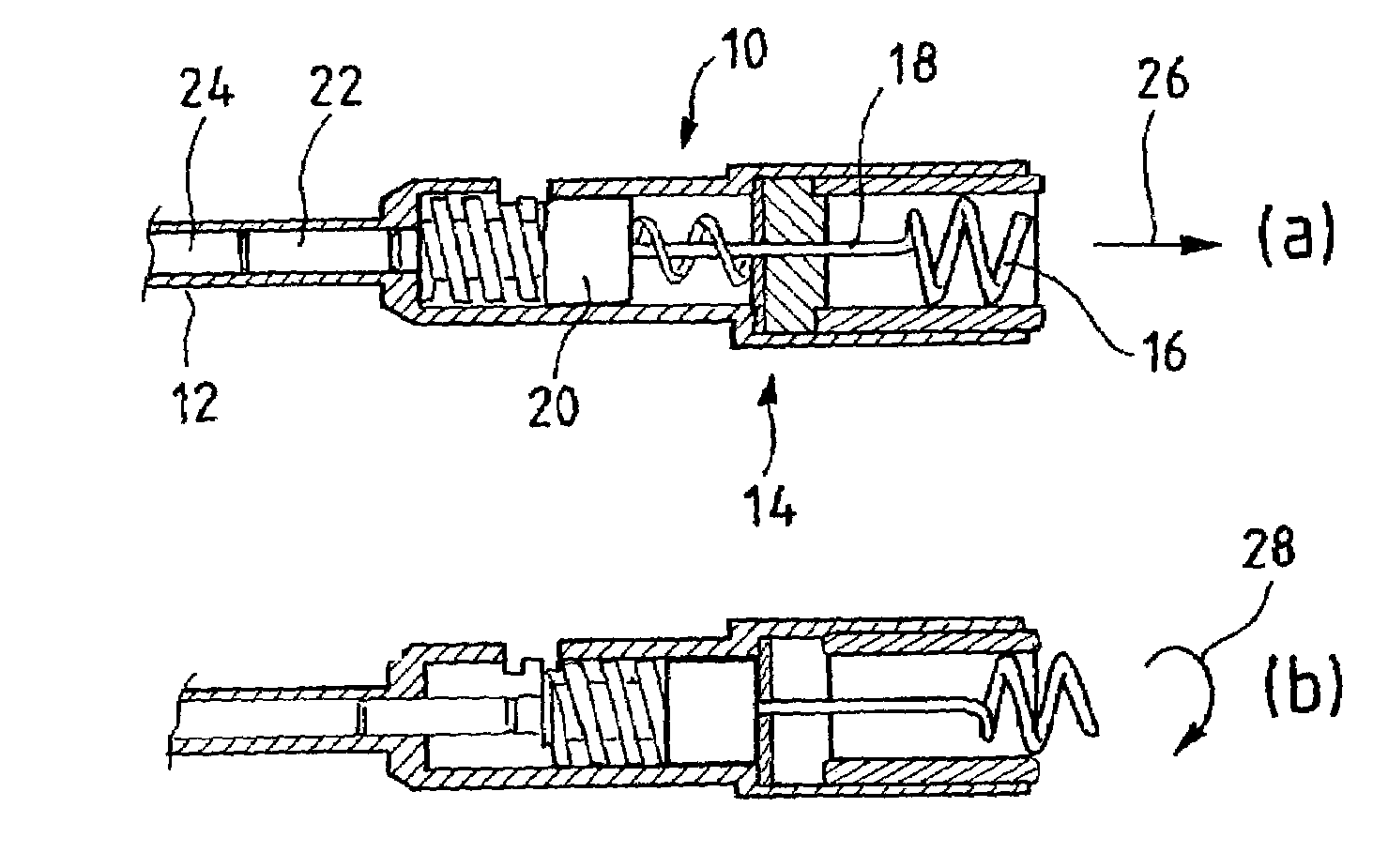
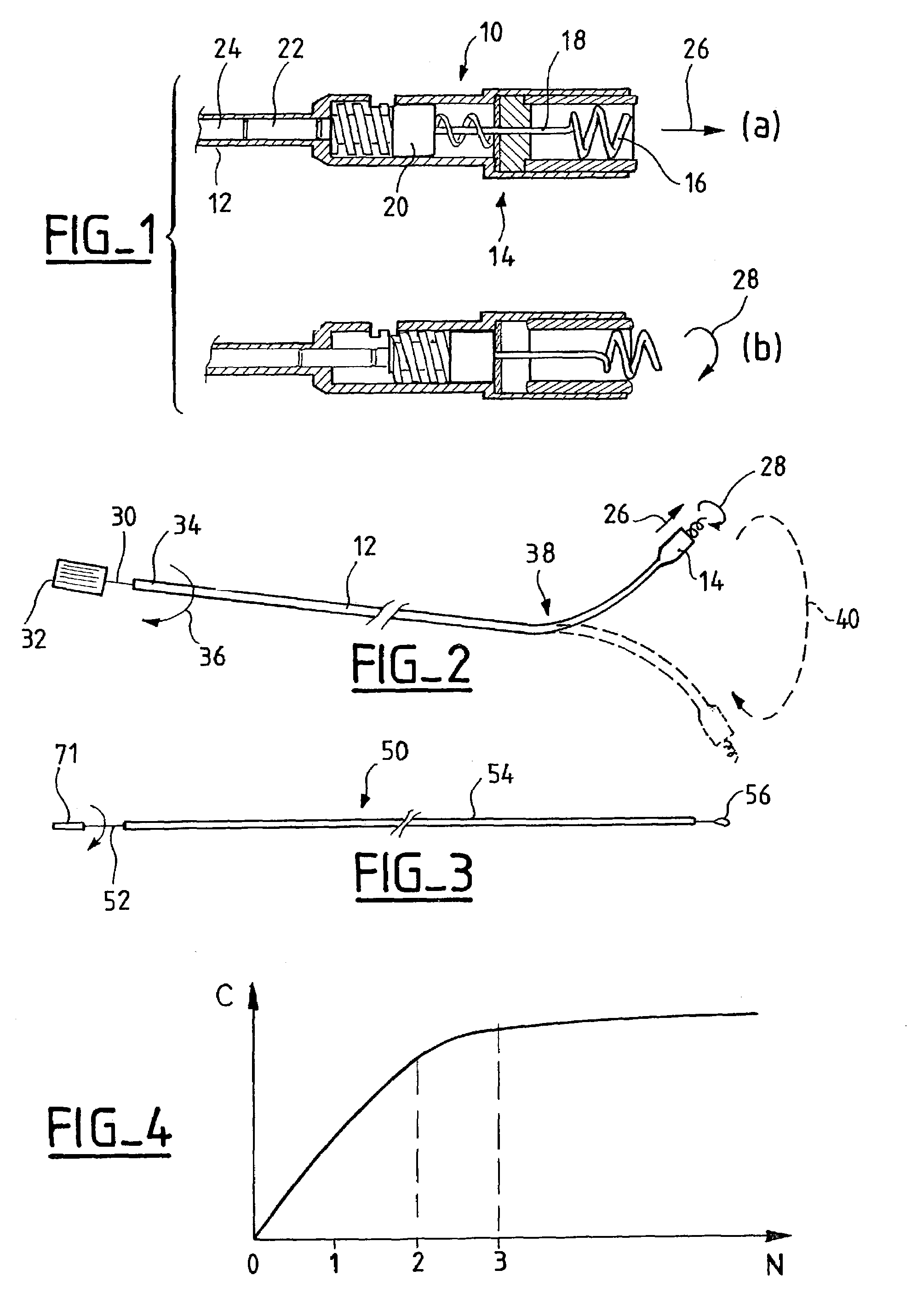
[0027]With reference to FIG. 1, a lead-head 10 of the type with a retractable screw 16 is shown, with screw 16 in a retracted position (FIG. 1a) and in a deployed position (FIG. 1b).

[0028]Lead-head 10 is assembled at the extremity of a sheath 12 which together constitute a lead-body. Sheath 12 has the shape of a flexible hollow tube incorporating one or more electrical wires, as are well known, and not represented. Lead-head 10 also has a mechanism 14 making it possible to deploy a screw 16 intended to anchor itself in the wall of the endocardium, in order to ensure a mechanical, and possibly a electrical connection (according to whether or not screw 16 is insulated), with the myocardium tissue, and to prevent any displacement or dislodgment of lead-head 10.

[0029]Screw 16 is placed at the extremity of a stem 18 interdependent of a mobile piston 20 inside lead-head 10. Piston 20 is prolonged in a proximal direction by a rod 22, which can engage with and be rotated by a screwdriver-st...


PUM


Abstract

A set for installing an intracardiac lead equipped with a screw in a wall of the endocardium, particularly a stimulation or defibrillation lead. This set comprises a removable stylet (50), able to be introduced inside the sheath (12) of the lead-body and mobile in translation and rotation therein. The stylet has at its distal extremity a mechanism (56) for coupling in rotation to allow the rotation (28) of the lead-head (10). The stylet (50) includes: a central core (52, 71) carrying at its distal extremity the aforementioned coupling mechanism, and at its proximal extremity a handling body (32) for handling by the physician and a hollow tube (54) axially placed around the core. The length of the hollow tube is less than the length of the core, so that the latter emerges from the hollow tube at the proximal and distal extremities of the tube, so as to allow the rotation of the core and correlatively of the coupling mechanism, by action on the handling body, primarily without setting in rotation of the hollow tube.

Description

FIELD OF THE INVENTION[0001]The present invention relates to the installation of the intracardiac leads for stimulation or defibrillation, and more particularly to the installation of the so-called “screw-in leads” (with or without a retractable screw), that are provided at their distal extremity with a screw allowing anchoring in the endocardium tissue at the contact point.BACKGROUND OF THE INVENTION[0002]Intercardiac leads are implanted in a cavity of the myocardium, and allow for the sensing of spontaneous depolarization signals, the application of stimulation pulses and / or a defibrillation or cardioversion shock produced by pacemaker, defibrillator, cardiovertor and / or “multisite” type device or, more generally, by an “active implantable medical device”, as such devices are defined by the Jun. 20, 1990 Directive 90 / 385 / CEE of the Council of the European Communities. EP-A-0 591 053 and its counterpart U.S. Pat. No. 5,447,534 describe such a screw-in lead, currently marketed by th...

Claims


Application Information

Patent Timeline
Patent Type & Authority Patents(United States)
IPC IPC(8): A61N1/05
CPCA61N1/0573A61N2001/058A61N2001/0578
Inventor OLLIVIER, JEAN-FRANCOISBESSOULE, FREDERIC
Owner SORIN CRM
Why Eureka
Try Eureka