Disk table rotation supporting structure

a technology of supporting structure and disk table, which is applied in the direction of record information storage, record carrier contruction details, instruments, etc., can solve the problems of large number of parts, complicated configuration of disk changer, and high number of rotational speed variations, so as to achieve quality stabilization, prevent variation in quality, and eliminate the effect of rotational speed variation

Inactive Publication Date: 2006-08-22
FUNAI ELECTRIC CO LTD
View PDF8 Cites 1 Cited by
  • Summary
  • Abstract
  • Description
  • Claims
  • Application Information

AI Technical Summary

Benefits of technology

[0012]It is an object of the present invention to make it possible to maintain a rotational speed of a disk table on a tray constant by eliminating variation in the rotational speed and also achieve stabilization of quality by preventing variation in the quality due to variation in parts.

Problems solved by technology

Therefore, its configuration of the mechanism becomes complicated.
However, as shown in respective drawings, this disk changer is complicated in configuration and the number of parts is very great.

Method used


Image

  • Disk table rotation supporting structure
  • Disk table rotation supporting structure
  • Disk table rotation supporting structure

Examples


Embodiment Construction

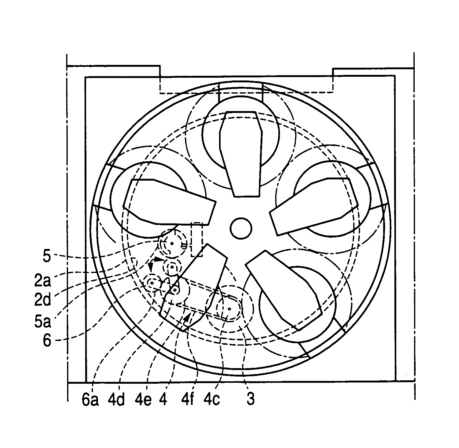
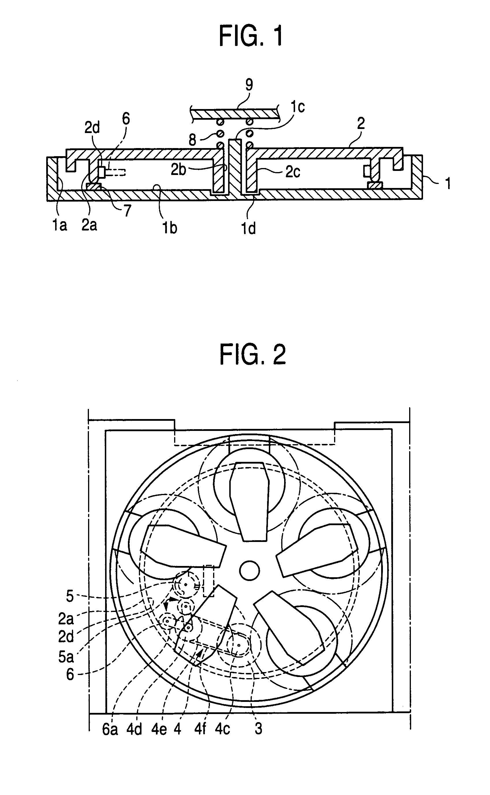
[0028]An embodiment of a disk table rotation supporting structure according to the present invention will be described with reference to the accompanying drawings. FIG. 1 is a sectional view showing a disk table rotation supporting structure. FIG. 2 is a partial plan view of a disk unit having the disk table rotation supporting structure.

[0029]As shown in FIG. 1, a disk table rotation supporting structure of the present embodiment includes a tray 1 that can be moved back and forth and has a circular inner wall surface 1a that stands upward, a bottom surface 1b provided on the inside of the inner wall surface, a central axis portion 1c that stands upward on the center portion of the bottom surface 1b, a receiving portion 1d having an annular recess shape and disposed around the central axis portion 1c, and a disk table 2 that can load a plurality of disks (not shown) thereon and has a large circular-ring supporting rib 2a provided downward in neighborhood of the inner wall surface 1a...


PUM

PropertyMeasurementUnit
length L3aaaaaaaaaa
length L1aaaaaaaaaa
rotational speedaaaaaaaaaa

Abstract

A disk table rotation supporting structure includes a tray having an inner wall surface that stands upward, a bottom surface provided on an inside, a central axis portion that stands upward on a center portion of the bottom surface, and a receiving portion disposed around the central axis portion, and a disk table having a large circular-ring supporting rib provided downward in neighborhood of the inner wall surface, a central through hole portion opened in a center portion and into which the central axis portion of the tray is inserted, and a small circular-ring rib extended downward from a periphery of the central through hole portion. Only the large circular-ring supporting rib is supported rotatably on the bottom surface of the tray via a lubricating member, and the disk table is rotated in this situation.

Description

BACKGROUND OF THE INVENTION[0001]1. Field of the Invention[0002]The present invention relates to a disk table rotation supporting structure on a tray.[0003]2. Description of the Related Art[0004]A first prior art is shown in FIG. 4, FIG. 5 and FIG. 6. A disk player includes a slide table 103 that is put in and out to slide in the horizontal direction of a housing 101, a rotary disk tray 104 mounted on the slide table 103 and on which a plurality of disk loading portions 104A that can house plural disks therein to align on the same planar surface are provided, a driving unit having a rotating motor 105 for rotating the rotary disk tray 104 to stop it at a predetermined position, a disk playing block 107 housed in the housing 101 to reproduce recording signals of the disk positioned at a playing position of the rotary disk tray 104, and a loading unit 109 for setting the slide table 103 and the disk playing block 107 to a loading position. A chucking head 106 one end of which is held ...

Claims


Application Information

Patent Timeline
Patent Type & Authority Patents(United States)
IPC IPC(8): G11B17/028G11B17/03G11B17/24G11B17/22G11B19/20
CPCG11B19/2009G11B17/226
Inventor YAMAGOSHI, YASUSHI
Owner FUNAI ELECTRIC CO LTD
Why Eureka
Try Eureka