Cascading closed loop cycle power generation

a closed loop cycle and power generation technology, applied in the direction of mechanical power devices, machines/engines, mechanical apparatus, etc., can solve the problems of dramatic inefficiencies, limited useful energy recovered, and little, if any, useful energy extracted, so as to improve the efficiency of the power system and increase the pressure of the working fluid

Inactive Publication Date: 2006-08-29
UNIVERSAL TECH
View PDF22 Cites 120 Cited by
  • Summary
  • Abstract
  • Description
  • Claims
  • Application Information

AI Technical Summary

Benefits of technology

[0019]In yet another embodiment, the present invention provides a method for improving the efficiency of a power system having an energy source and a cooling system. The method includes the steps of transferring a first amount of heat energy from the cooling system to a first loop of a cascading closed loop cycle system; extracting a first amount of useful energy from the first loop; transferring a second amount of heat energy from the energy source to a second loop of a cascading closed loop cycle system; and extracting a second amount of useful energy from the second loop.
[0021]In another embodiment, the present invention provides a method for improving the efficiency of a power system having an energy source and a cooling system. The method has the steps of providing a working fluid; increasing the pressure of the working fluid; dividing the working fluid into multiple streams, including at least a first stream and a second stream; transferring a first amount of heat energy from the cooling system to the first stream; extracting a first amount of useful energy from the first stream; transferring a second amount of heat energy from the energy source to the second stream; extracting a second amount of useful energy from the second stream; and cooling the working fluid to a minimum pressure, the minimum pressure being approximately equal to or below the vapor pressure of the working fluid at an ambient air temperature.
[0025]In yet another embodiment, the present invention provides a method for improving the efficiency of a power system having an energy source and a cooling system. The method of this embodiment includes: providing a working fluid; increasing the pressure of the working fluid; dividing the working fluid into a first stream a second stream and a third stream; transferring a first amount of heat energy from the cooling system to the first stream; extracting a first amount of useful energy from the first stream; transferring a second amount of heat energy from the energy source to the second stream; extracting a second amount of useful energy from the second stream; transferring a third amount of heat energy from the second stream to the third stream; extracting a third amount of useful energy from the third stream; and cooling the working fluid to a minimum pressure, the minimum pressure being approximately equal to or below the vapor pressure of the working fluid at an ambient air temperature.

Problems solved by technology

The thermodynamic requirements of the steam cycle limit the temperature differential available to produce superheated steam to the difference between the original heat source temperature and approximately 400 to 500° F. This results in wasted heated flue gas exiting the boiler at temperatures of about 400 to 500° F. Although a portion of the energy in the flue gas exhaust may be recaptured by, for example, using it to heat the power plant, using it to pre-heat the boiler water, or by other known means, the amount of useful energy recovered is limited.
As such, little, if any, useful energy can be extracted from a vapor that only contains the latent heat of vaporization because such vapor will immediately condense upon expansion in a turbine, causing dramatic inefficiencies and possibly damaging the turbine.
The physical phenomenon of the heat of vaporization causes waste heat in conventional power generation cycles because this amount of heat must be imparted into the liquid water before it changes into a useful gaseous state but this heat can not be extracted as useful energy.
Thus, the thermal energy discharged to the atmosphere through the cooling medium that returns the water to the liquid state is waste heat.
In addition, the negative effects on the environment caused by pollution generated from the combustion of fossil fuels dictates that power plants be designed to reduce the pollutants generated per unit of energy produced.
Steam boilers are generally limited to recovering the thermal energy associated with the differential temperature between the initial temperature of the heat source and about 500° F. or higher because this is the temperature required to achieve efficient thermal energy transfer to water to produce steam.
Further, the available heat for transferring energy to the steam is limited by the temperature differential restrictions imposed by the vapor pressure versus temperature characteristics of steam, and using a heat source with a temperature close to about 500° F. can lead to inefficient and minimal steam production.
However, only a limited amount of the heat in the discharge air is recoverable, and this heat is generally restricted to the temperature differential between the ˜500° F. discharge temperature of the heat source exhaust and about 300° F. or above due to the vapor pressure and temperature characteristics of water.
These conventional ORC media have pressure and temperature limitations and can not sustain high temperatures due to their respective auto ignition temperatures and vapor pressure versus temperature characteristics.
For example, prior art ORC systems that utilize refrigerants or toluene are restricted to operation with heated water since the ORC medium can not absorb energy at elevated temperatures.
These limitations reduce their effectiveness and efficiency thereby restricting the circumstances under which they can be employed, and limiting the useful energy output that may be obtained from them.

Method used


Image

  • Cascading closed loop cycle power generation
  • Cascading closed loop cycle power generation
  • Cascading closed loop cycle power generation

Examples


Embodiment Construction

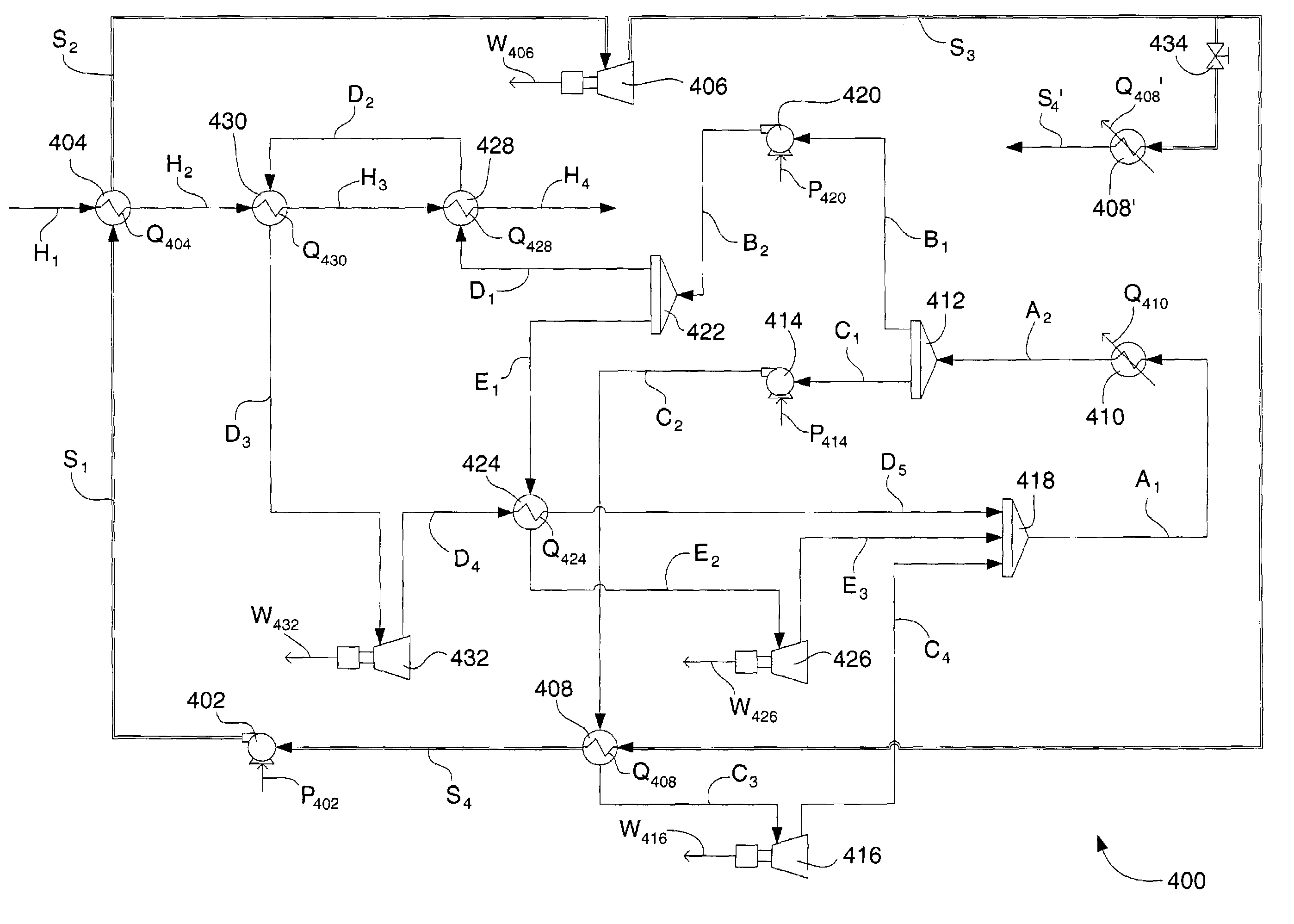
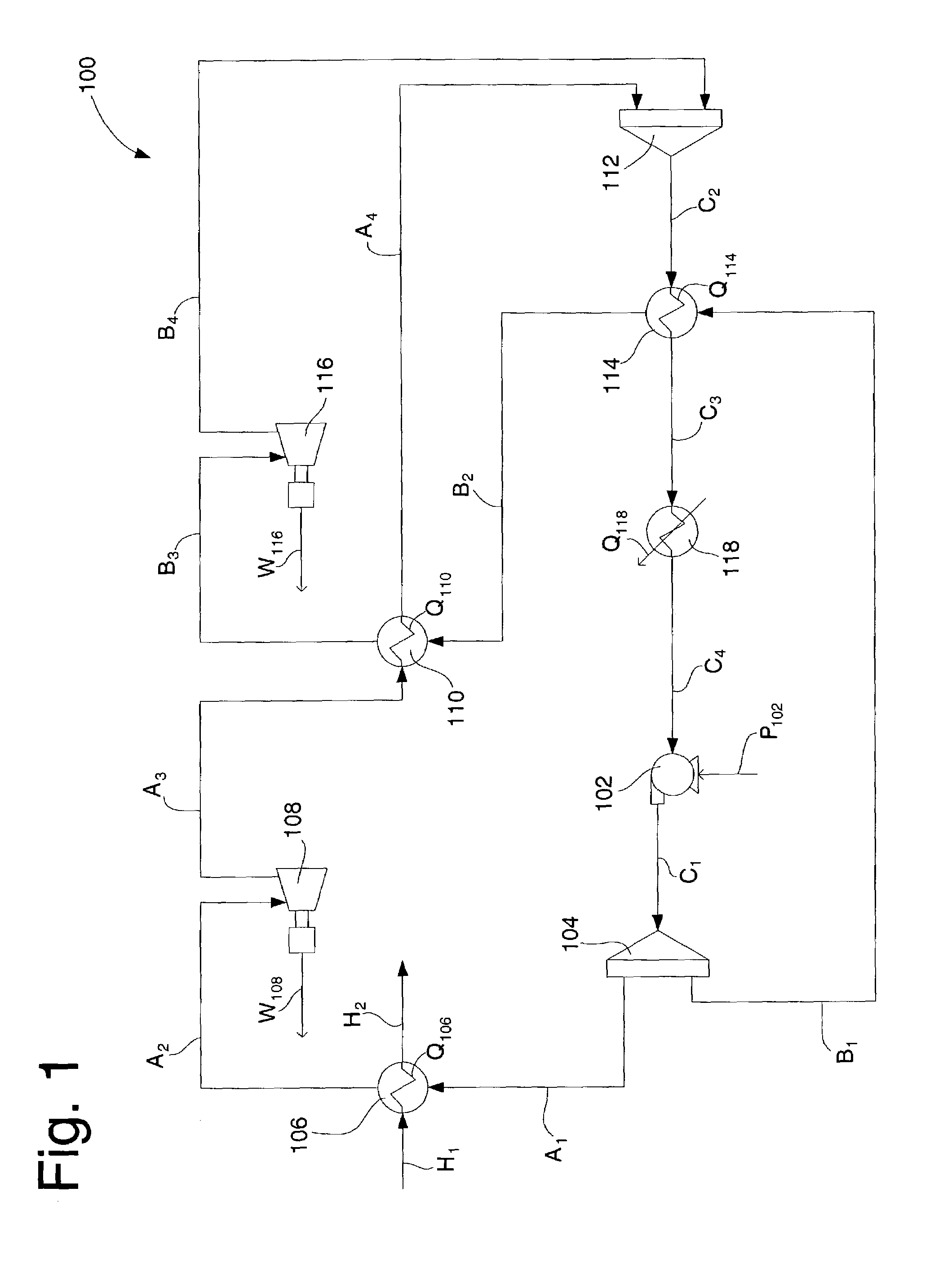
[0038]Developing electricity in a more efficient manner is of paramount importance as energy sources are depleted and the pollution generated from the combustion of fossil fuels continues to harm the environment. The Cascading Closed Loop Cycle of the present invention provides a closed loop power generation system that may be used as a primary power source. With the CCLC, improved efficiency is provided by reducing the amount of energy lost to overcome the latent heat of vaporization of the power generation medium and more effectively capturing heat from available heat sources and converting this heat to useful energy. The Super Cascading Closed Loop Cycle (Super-CCLC) of the present invention offers a secondary power source that can be used in conjunction with conventional power systems to increase power generation efficiency by generating useful energy from the heat lost in the process of generating power using steam turbines or other conventional power systems. In the Super-CCLC...


PUM


Abstract

Cascading Closed Loop Cycle (CCLC) and Super Cascading Closed Loop Cycle (Super-CCLC) systems are described for recovering power in the form of mechanical or electrical energy from the waste heat of a steam turbine system. The waste heat from the boiler and steam condenser is recovered by vaporizing propane or other light hydrocarbon fluids in multiple indirect heat exchangers; expanding the vaporized propane in multiple cascading expansion turbines to generate useful power; and condensing to a liquid using a cooling system. The liquid propane is then pressurized with pumps and returned to the indirect heat exchangers to repeat the vaporization, expansion, liquefaction and pressurization cycle in a closed, hermetic process.

Description

[0001]This is a continuation-in-part of U.S. patent application Ser. No. 10 / 199,257, filed on Jul. 22, 2002 now U.S. Pat. No. 6,857,268.FIELD OF THE INVENTION[0002]The present invention relates to apparatus and methods for generating energy. More specifically, the present invention relates to the use of a Cascading Closed Loop Cycle employing particular devices and fluids that may be used in combination with conventional power generation systems to extract a useful amount of additional energy from the conventional power generation process.BACKGROUND OF THE INVENTION[0003]The primary process used to generate electricity is the combustion of a fossil fuel to heat air. This high temperature air, or thermal energy, is then used to heat a liquid power generation medium (typically water) in a boiler to create a gas (steam) that is expanded across a steam turbine that drives an electrical generator. The measure of the thermal energy is the British Thermal Unit (BTU). Other sources of energ...

Claims


Application Information

Patent Timeline
Patent Type & Authority Patents(United States)
IPC IPC(8): F01K25/08F01K1/00F01K25/00F01K7/34F03G7/00
CPCF01K25/08Y02P80/15
Inventor STINGER, DANIEL H.MIAN, FAROUK ASLAM
Owner UNIVERSAL TECH
Why Eureka
Try Eureka