Wiper plug with packer

a technology of wiper plugs and packers, which is applied in the direction of sealing/packing, fluid removal, borehole/well accessories, etc., can solve the problems of diaphragm rupture, pump fouling, and interference with well operation

Inactive Publication Date: 2006-08-29
TESSIER LYNN P +2
View PDF6 Cites 23 Cited by
  • Summary
  • Abstract
  • Description
  • Claims
  • Application Information

AI Technical Summary

Benefits of technology

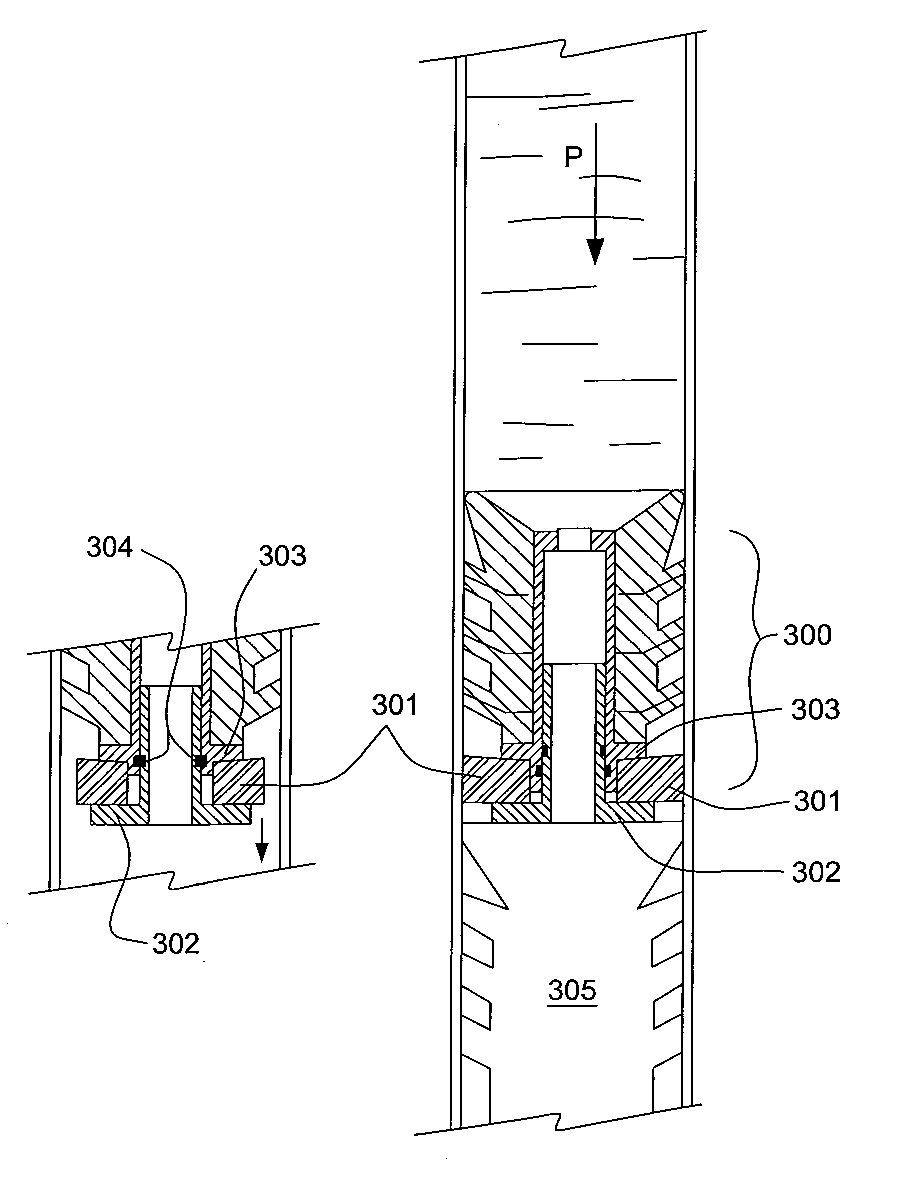
[0021]In another aspect, the incorporation of a packer element into the wiper plug enables a method of cementing a casing into a wellbore without the need for a float shoe or other one way valves. The method comprises: pumping a bottom plug to the bottom of a casing string until the plug is landed on the guide shoe or float collar; pumping a column of cement; pumping a top plug following the cement; pumping displacement fluid to force the column of cement to open a rupture element or valve in the bottom plug to cause the cement to be displaced into the wellbore annulus; and pumping displacement fluid to actuate the packer element in the top plug to the expanded diameter for sealing against the casing and preventing cement from re-entering or U-tubing into the casing bore.
[0022]Advantageously, when running in the casing, the casing will fill with displacement fluid by itself without having to stop every 200–300′ to add fluid, therefore it is no longer necessary to provide a one way valve to prevent fluid rising in the casing. Only when the top plug rests on the bottom plug and the packer is set is fluid prevented from rising in the casing.
[0023]In another embodiment, a method of cementing and sealing the wellbore from leakage of fluids below the perforations is provided, comprising: pumping a bottom plug to the bottom of a casing string until the plug is landed on the guide shoe; pumping a column of cement; pumping a top plug following the cement; pumping displacement fluid to force the column of cement to open a rupture element in the bottom plug to cause the cement to be displaced into the wellbore annulus; pumping displacement fluid to actuate the packer element in the top plug to the expanded diameter for sealing against the casing and preventing cement from re-entering into the casing; permitting the cement to harden and cure; and perforating the casing above the top plug, the packer element preventing leakage uphole past the top plug.

Problems solved by technology

In the course of cementing the casing, components are placed in the well which can later migrate and possibly interfere with well operations.
An increase in fluid pressure above the supported bottom plug results in the diaphragm rupturing, allowing the cement slurry to pass though the bottom plug and continue out the bottom of the casing, beginning to fill the annular space between the casing and the well bore.
Applicant is aware that in many cases, often a year or more after the cementing of the casing, the top cementing plug can migrate up the production casing to the pump intake and cause fouling of the pump.
Applicants believe that during perforation of the casing, the cement surrounding the plugs and outside the casing may be fractured.
If sufficient fracturing occurs, the plugs are no longer held securely inside the casing and can migrate upwards.
If one-way valves in the float equipment are also damaged as a result of pressure pulses during perforation, are washed out during cementing or have material trapped therein, against a seat, preventing closure, then the plugs may be forced upwards due to the increased pressure from below.
Traditionally, whenever the pump intakes are fouled, production is lost and the tubing is tripped out of the well to repair the pump, at great expense.
Whether repairing the pump or setting a bridge plug, significant expense is involved in both equipment and rig time.
However, when used as a top wiper plug, differential pressure across the plug can cause fluids to flow from a lower zone which is undesirable once the top wiper plug has been set.

Method used


Image

  • Wiper plug with packer
  • Wiper plug with packer
  • Wiper plug with packer

Examples


Embodiment Construction

The Self-Retaining Wiper Plug

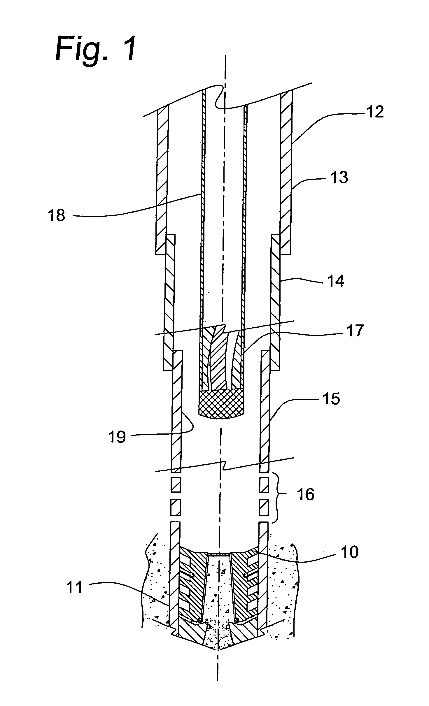
[0039]Having reference to FIG. 1, a cementing plug 10 is shown positioned adjacent a bottom 11 of a casing string 12 comprising, in order beginning from surface (not shown): surface casing 13, intermediate casing 14 and production casing 15. The cementing plug 10 is located below a plurality of perforations 16 in the production casing 15 and below a pump 17 lowered into the casing 12 at the end of a production string 18.

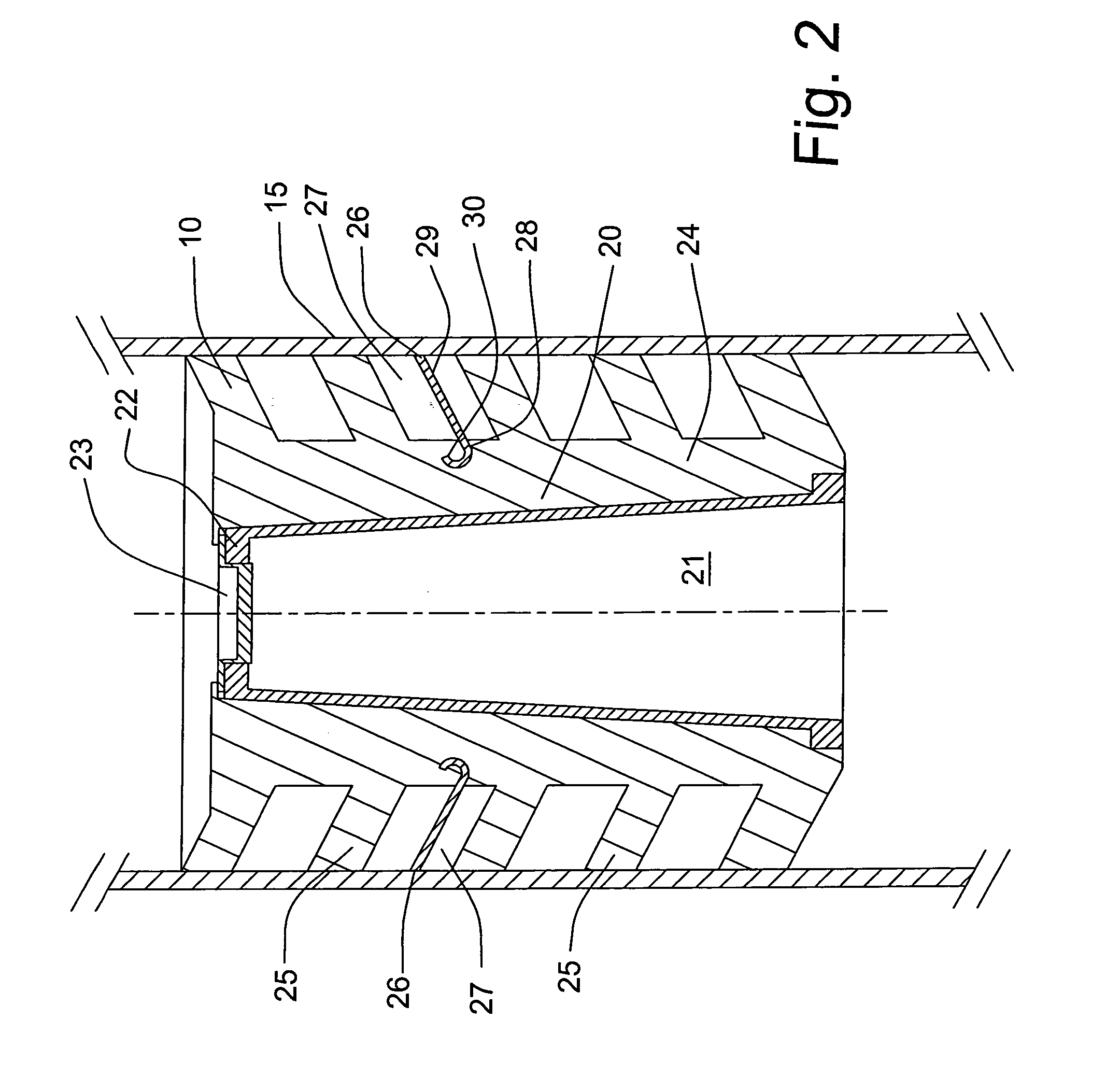
[0040]As shown in FIG. 2, and in a preferred embodiment of the invention, the cementing plug 10 comprises a core 20. The core 20 is covered with an elastomeric covering 24 having a plurality of wipers 25 formed thereon. Preferably, the core 20 defines a bore 21 therethrough. A top end 22 of the core 20 is fitted with a rupture element 23 to permit the passage of cement slurry during cementing should the plug 10 be used inadvertently as a bottom wiper plug. Typically, the rupture element 23 is designed to rupture only at a predetermined pr...


PUM


Abstract

A self-retaining cementing wiper plug with a packer element has two or more steel or carbide tipped holddown fingers or slips extending radially outward from the plug for engaging the inner surface of the casing and preventing the plug from moving uphole over time and potentially interfering with other downhole apparatus such as a pump. The packer element in the wiper plug is actuated when the plug is supported by an obstruction under the plug and then compressed, the packer being maintained in compression by the holddown fingers.

Description

CROSS REFERENCE TO RELATED APPLICATION[0001]This application is a regular application claiming priority of U.S. Provisional Patent application Ser. No. 60 / 499,716, filed on Sep. 4, 2003, the entirety of which is incorporated herein by reference.FIELD OF THE INVENTION[0002]The invention relates to cementing wiper plugs used in cementing casing downhole and particularly to top cementing plugs used for cementing production casing and further to wiper plugs integrating a packer for preventing uphole fluid flow from a lower zone.BACKGROUND OF THE INVENTION[0003]It is conventional practice, in the drilling and completion of wells, to case an open hole by cementing tubular casing in place in a wellbore. Thus, the open hole is prevented from caving in, fragile formations are protected, inter-zonal communication is restricted and contamination of groundwater is prevented. In the course of cementing the casing, components are placed in the well which can later migrate and possibly interfere w...

Claims


Application Information

Patent Timeline
Patent Type & Authority Patents(United States)
IPC IPC(8): E21B23/10E21B33/12E21B33/16
CPCE21B33/16
Inventor WEBER, JAMES L.TESSIER, LYNN PDOYLE, JOHN P.
Owner TESSIER LYNN P
Why Eureka
Try Eureka