Inner ratchet chain tensioner

Inactive Publication Date: 2007-03-08
DAIDO KOGYO CO LTD
View PDF4 Cites 18 Cited by
  • Summary
  • Abstract
  • Description
  • Claims
  • Application Information

AI Technical Summary

Benefits of technology

[0017] A retaining ring to press and fix a flange part of the flanged cylindrical body is fitted to an outer periphery of the bottom of the cylinder, and the ri

Problems solved by technology

That is, it is necessary that a register ring is put, and a groove is provided to ensure its locking surface, and in the case where the register ring is put in the outer peripheral part of the plunger, a cylindrical body having a stop locking surface at its outer peripheral part is required to be inserted into the housing, and the outer diameter of the housing becomes inevitably large.
Sin

Method used


Image

  • Inner ratchet chain tensioner
  • Inner ratchet chain tensioner
  • Inner ratchet chain tensioner

Examples


Embodiment Construction

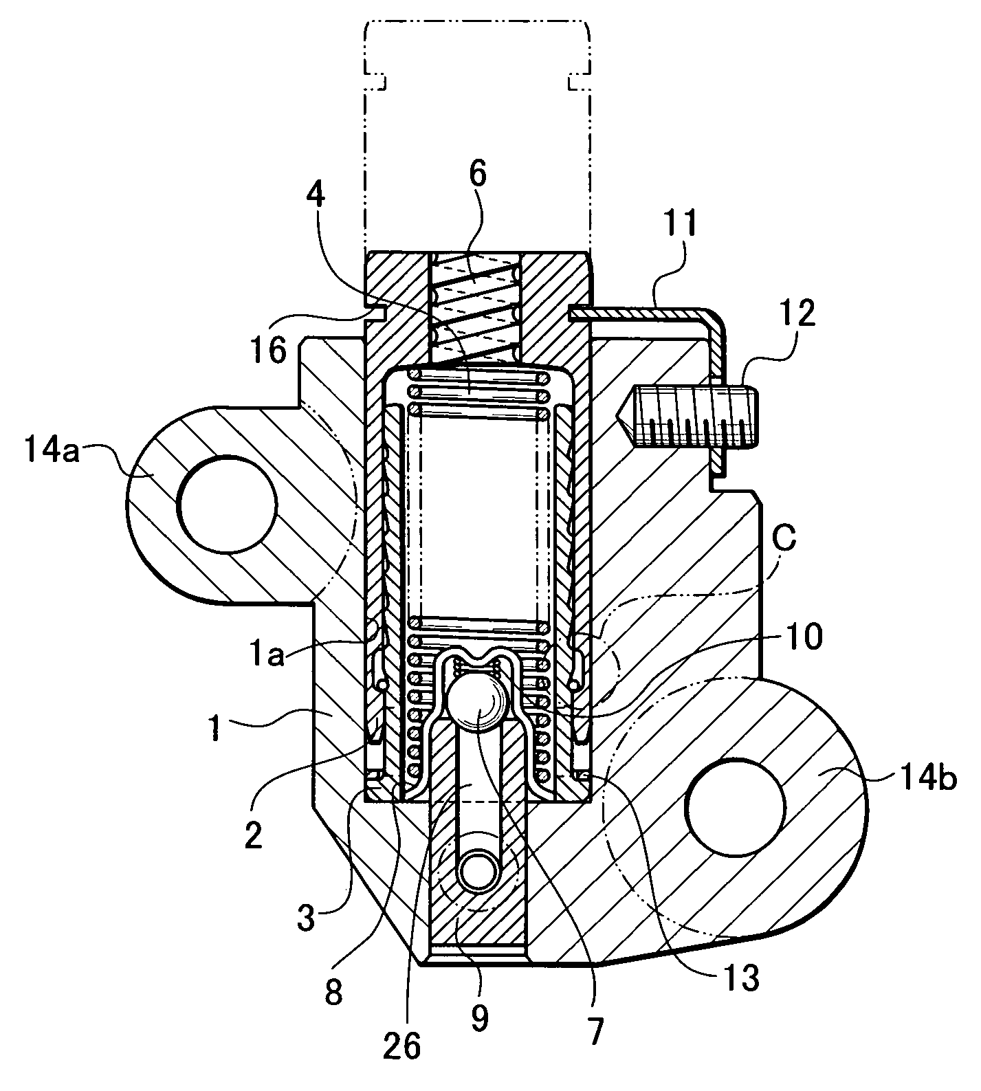
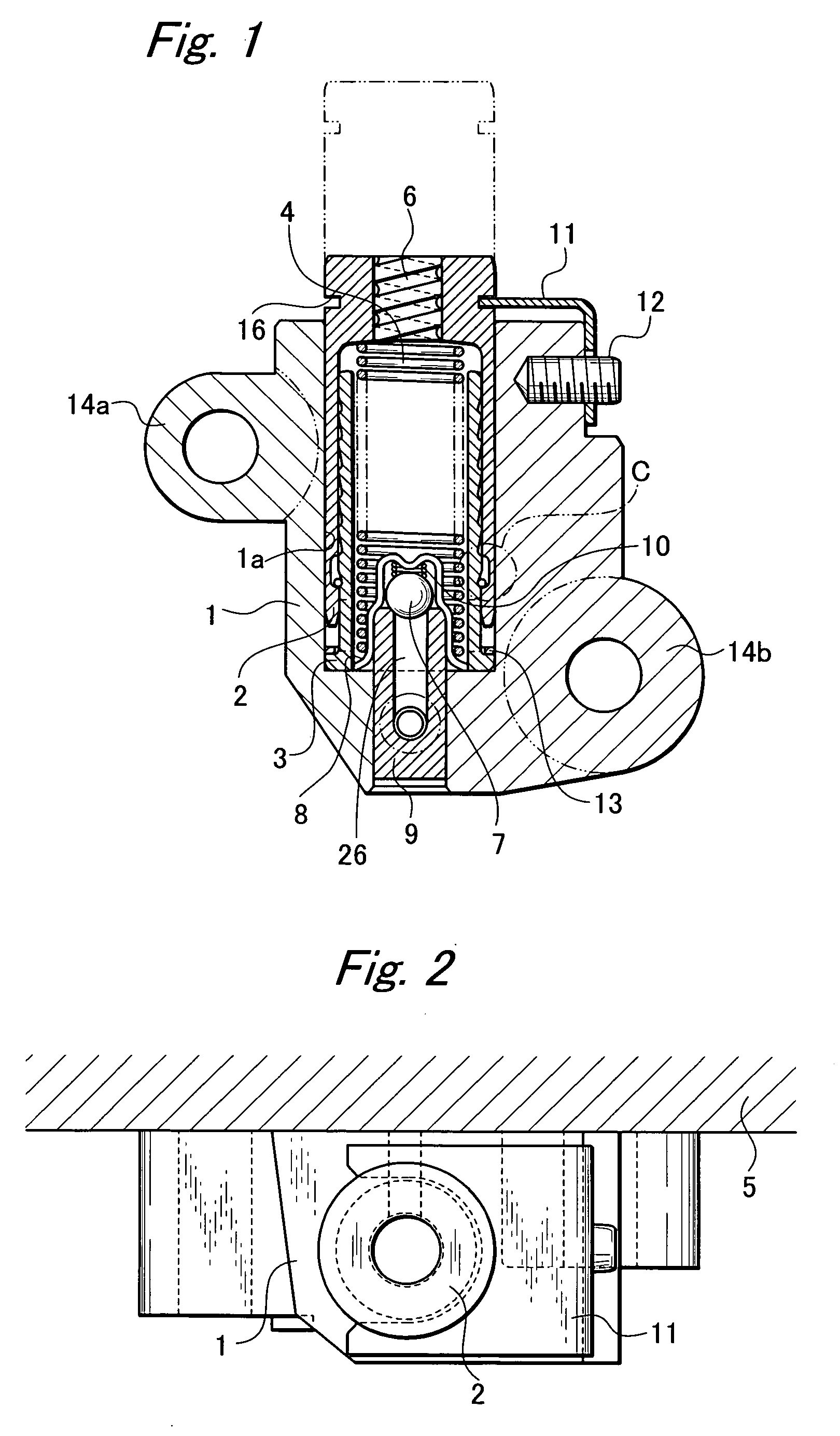
[0031] As shown in FIGS. 1 and 2, an inner ratchet chain tensioner according to an embodiment of the invention includes a housing 1 as a die casting block in which a cylindrical cylinder 1a is formed, a plunger 2 contained in the cylinder 1a, a flanged cylindrical body 3 which erects from the bottom of the cylinder 1a and on the outer periphery of which the plunger 2 is slidably fitted, a return spring 4 disposed in the flanged cylindrical body 3, and a ratchet mechanism to prevent retraction of the plunger. The housing 1 includes attachment parts 14a and 14b in which attachment holes for attachment to an engine block 5 are formed.

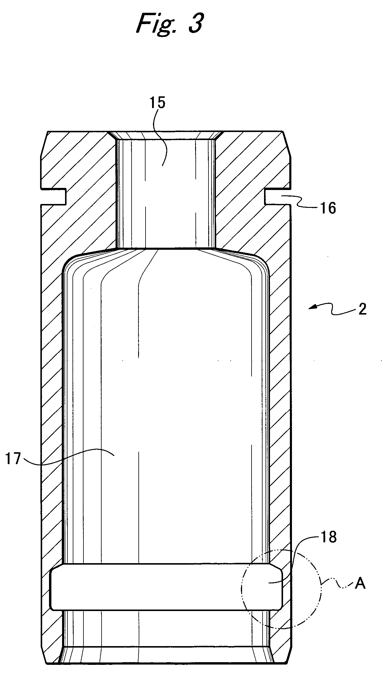
[0032] As shown in FIG. 3, a press-in hole 15 into which an air draw 6 is pressed is formed in the upper end part of the plunger 2, and a lock groove 16 is formed in the upper end outer periphery. The tip of a jumping-out preventing plate 11 attached to a spring pin 12 is locked in the lock groove 16, so that the plunger 2 fitted in the cylinder 1 a of th...


PUM


Abstract

In order to provide a plunger retraction preventing mechanism and to reduce the outside dimension of a housing, an inner ratchet chain tensioner includes a housing in which a cylinder is formed, a cylindrical plunger having a bottom and slidable in the cylinder by oil pressure, a flanged cylindrical body erecting from a bottom of the cylinder and on an outer periphery of which the plunger is slidably fitted, a return spring contained in the flanged cylindrical body to urge the plunger in a protruding direction, and a ratchet mechanism to prevent retraction of the plunger, and the ratchet mechanism includes a register ring containing groove formed on an inner peripheral part of the plunger, plural circumferential grooves formed at constant intervals on an outer periphery of a tube part of the flanged cylindrical body, and a register ring fitted between the register ring containing groove and the circumferential groove.

Description

BACKGROUND OF THE INVENTION [0001] 1. Field of the Invention [0002] The present invention relates to a hydraulic chain tensioner to prevent looseness of a gearing chain. [0003] 2. Related Art [0004] In the case where a chain constructed of plural links connected to each other is stretched over a sprocket and transmits motive power, a coupling part of each of the links is worn down and elongation occurs. In a roller chain exposed to the outside and stretched so as to drive a rear wheel of a motorcycle, it is possible to deal with the elongation by adjusting the position of the sprocket. However, in the case of, for example, a timing chain used in the inside of an engine, a chain tensioner is attached, and fluttering of the chain caused by the elongation and excessive tensile force caused by the fluttering are prevented. [0005]FIG. 11 shows a conventional general chain tensioner, which includes a housing “a” and a plunger “b” provided to be slidable in the housing “a”. Hydraulic oil “...

Claims


Application Information

Patent Timeline
IPC IPC(8): F16H7/08F16H7/22
CPCF16H7/0848F16H2007/0806F16H2007/0812F16H2007/0878F16H2007/0855F16H2007/0859F16H2007/0853
Inventor YAMADA, AKIRA
Owner DAIDO KOGYO CO LTD
Why Eureka
Try Eureka