Over-voltage protection circuit for a switched mode power supply

a protection circuit and power supply technology, applied in the direction of electric variable regulation, process and machine control, instruments, etc., can solve problems such as circuit component destruction

Active Publication Date: 2008-05-27
INTERDIGITAL MADISON PATENT HLDG
View PDF11 Cites 18 Cited by
  • Summary
  • Abstract
  • Description
  • Claims
  • Application Information

AI Technical Summary

Benefits of technology

[0009]The comparator output of the integrated controller circuit provides a slowly changing control information, with regard to the switching frequency of the switched mode power supply, which is used internally by the controller circuit for controlling the turn-off time of the switching transistor. This output voltage lies therefore during normal operating conditions within a small voltage interval, and only during fast load or voltage transitions, for example when switching on the power supply, this voltage steps to its maximum or minimum level for a short time. With the integrating circuit, these special operating conditions are levelled out, and only when the output voltage of the comparator keeps its extreme voltage level for a longer time period, the comparating circuit of the protection circuit becomes active and switches off the switched mode power supply.
[0011]The switched mode power supply comprises therefore a protection circuit, which avoids a rise of the output voltage to intolerable values in case of a failure of the feedback regulation loop for the output power regulation. This would lead to the destruction of circuit components. This protection circuit operates independently of any over-voltage protection circuits already included in the integrated controller circuit. Because the integrating circuit is in particular sensitive to an extreme voltage level of the feedback loop for a longer time period, the comparating circuit of the protection circuit monitors all conditions which could be dangerous to the switched mode power supply or other circuit components.

Problems solved by technology

This would lead to the destruction of circuit components.

Method used


Image

  • Over-voltage protection circuit for a switched mode power supply
  • Over-voltage protection circuit for a switched mode power supply
  • Over-voltage protection circuit for a switched mode power supply

Examples


Embodiment Construction

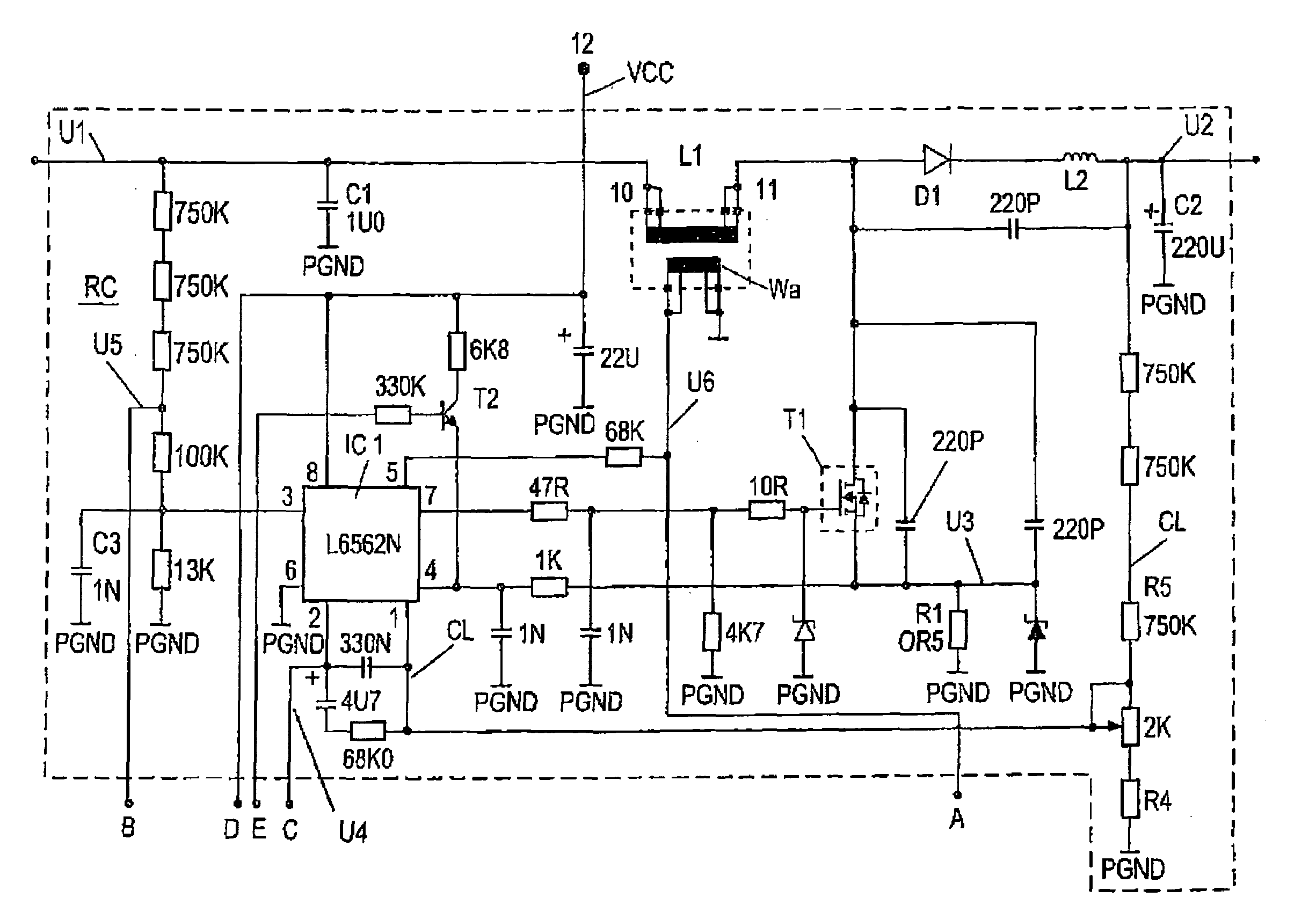
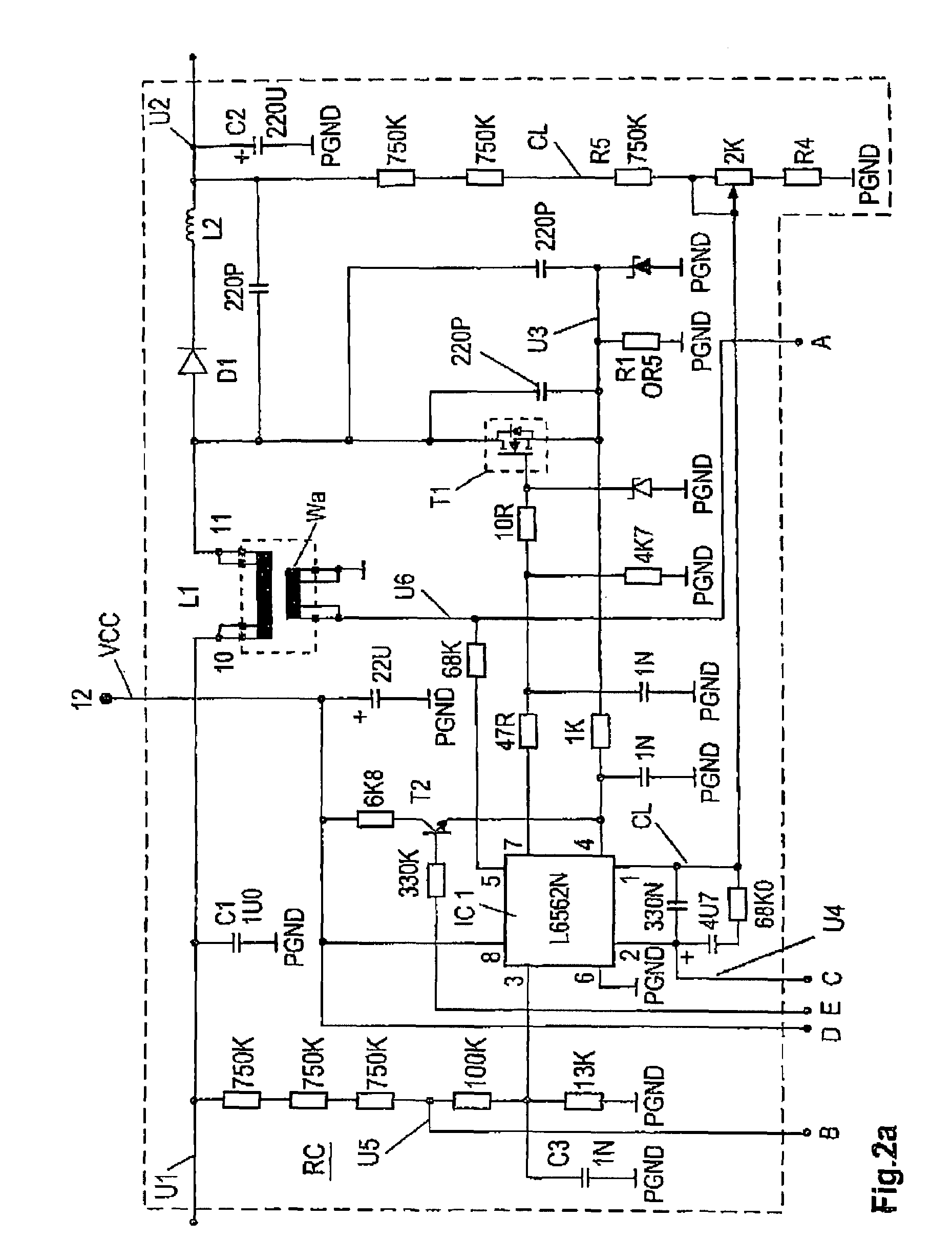
[0017]In FIG. 2a a switched mode power supply is shown operating with an input voltage U1. The voltage U1 is in particular a rectified voltage, provided for example by a bridge rectifier, not shown, connected to a mains supply voltage. For a reduction of interference noise, the voltage U1 is filtered by a capacitor C1. As an input voltage U1 also a smoothed DC voltage may be used.

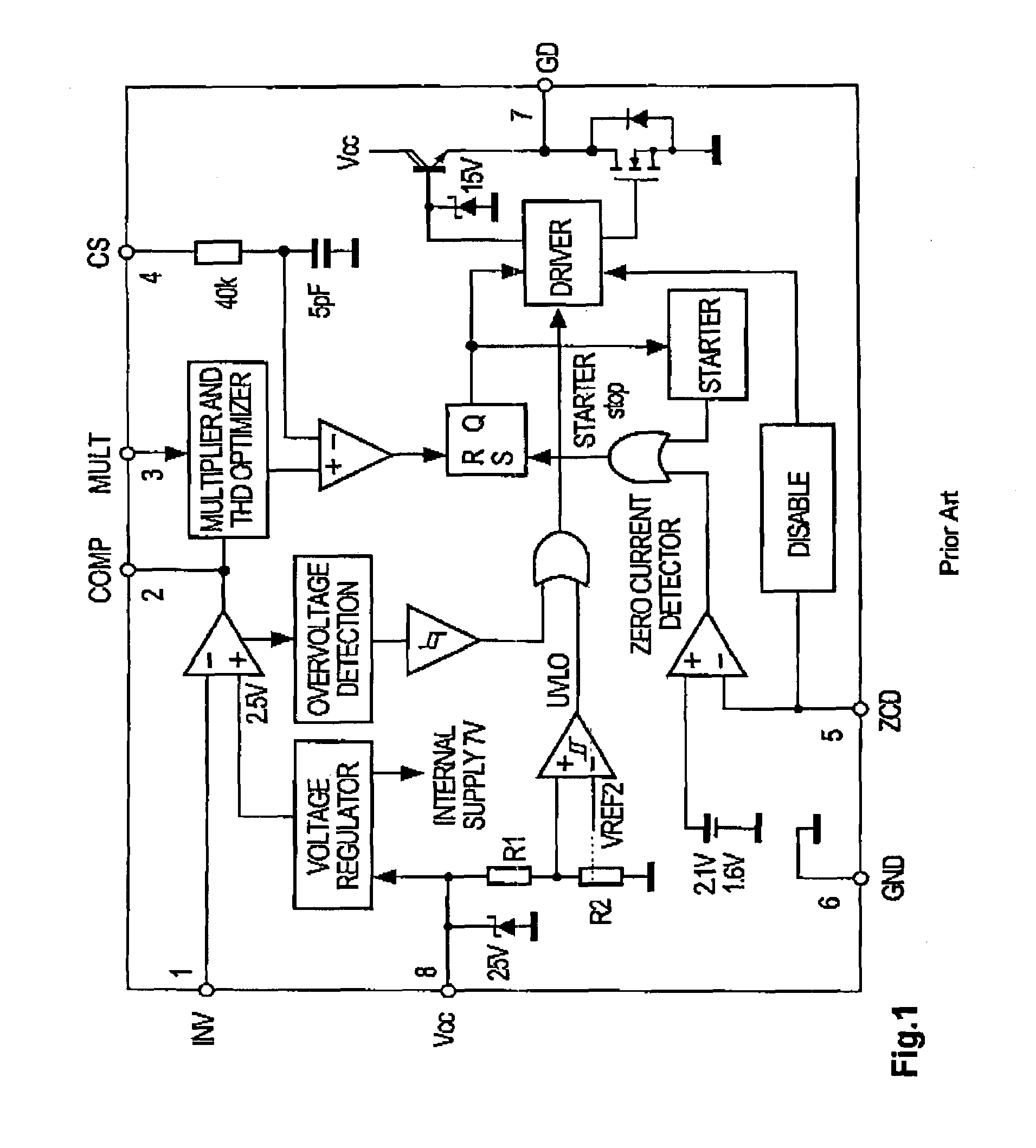
[0018]The input voltage U1 is coupled to an input terminal 10 of an inductor L1, which is coupled with an output terminal 11 to a switching power transistor T1, in this embodiment a MOSFET. The current output of the switching transistor T1 is coupled via a low impedance sense resistor R1 to a reference potential, in this embodiment to ground. The switching transistor T1 is operated by an integrated controller circuit IC1, which is coupled with a driver output 7 to a control input of the switching transistor T1.

[0019]To the output terminal 11 of the inductor L1 is further coupled a rectifying means D1, a tra...


PUM


Abstract

The switched mode power supply comprises an inductor, a switching transistor, a controller circuit coupled to the switching transistor, a rectifying means and a feedback regulation loop for providing a stabilised output voltage. It comprises further a protection circuit coupled to an output or input of a comparator of the controller circuit for providing an overvoltage protection in case of a failure of the regulation loop. The protection circuit comprises in particular an integrating circuit and a comparating circuit. In a preferred embodiment, an output of the protection circuit is coupled to a sense input of the controller circuit, for switching off the controller circuit immediately in case of a failure. In another aspect of the invention, the protection circuit comprises further a second comparator coupled to the first comparating circuit for the surveillance of the input voltage of the switched mode power supply, and for the detection of a short circuit of the inductor or the rectifying means.

Description

[0001]This application claims the benefit, under 35 U.S.C. § 119 of European Patent Application 04009677.8, filed Apr. 23, 2004.FIELD OF THE INVENTION[0002]The invention relates to a switched mode power supply providing a regulated output voltage, which comprises protection circuits against failures, for example for over-voltage protection. In particular, the invention relates to an upconverter circuit, applicable as a power factor correction pre-converter.BACKGROUND OF THE INVENTION[0003]It is well known to equip switched mode power supplies with protection circuits, for example for over-voltage protection, over-current protection, low mains voltage, or short circuit protection. Power supplies comprising an integrated controller circuit are already provided with respective protection circuits.[0004]In several countries it is now required to equip switched mode power supplies with a power factor correction (PFC), for reducing the permissible low frequency harmonic content of the wav...

Claims


Application Information

Patent Timeline
Patent Type & Authority Patents(United States)
IPC IPC(8): H02H7/10H02H3/20H02H7/00G05F1/40H02H3/28H02M1/00H02M1/32
CPCH02M1/32
Inventor LOUVEL, JEAN-PAULLOPEZ, DANIELGRELLMANN, HARALD
Owner INTERDIGITAL MADISON PATENT HLDG
Why Eureka
Try Eureka